The Manufacturing Cost of any part depends mainly on the part’s design. Two ways to approach design are –
- Focusing on the manufacturing cost associated with the part, such as the quality of material (cheapest or expensive), relaxing or tightening the tolerances, etc.
- Optimizing design by taking a holistic approach analyzing manufacturing feasibility, material properties, simple manufacturing processes, etc.
The first kind of approach delivers a vulnerable functional part when choosing the cheapest material or relaxed tolerance or a cheap manufacturing process. Part cost can be saved on paper, but in operation, it loses more money due to rejection, scrap, or in some cases, rejection of complete assembly. Secondly, expensive material, tight tolerances, and most reliable manufacturing processes will lead to high cost.
The second approach will result in the design of a part considering all the inputs, functional requirements, manufacturing process, and feasibility.
Remember that simple errors in the designing process can add up to millions of dollars or more direct, indirect, and opportunity costs. So, the idea is to identify early manufacturing feasibility, design failure, etc.
Design for manufacturing (DFM) is a methodology that involves designing to reduce the cost of production and time-to-market without compromising the quality of the product. DFM minimizes defects and rework and, in the process, saves costs and shortens time to market.
Design engineers having less experience often are not familiar with all the manufacturing process requirements and downstream process parameters. During the design stage, decisions made by engineers have cascading implications on product cost, quality, and time to market. As a result, engineering changes happen too late when issues are detected during manufacturing or assembly—and it will be costly to modify the designs.
Case Studies
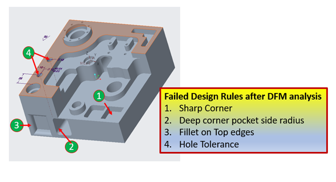
Let’s understand some examples for a machined part: As shown in Figure 1 below, there are 4 cases where designers can save manufacturing time and cost.
1. Milling a simple pocket with a sharp side corner radius:
The functional requirement for such a pocket may be to accommodate rectangular male counterparts for a male-female joint in an assembly. Creating an external sharp corner with CNC machining is easy; however, this is not true for an internal sharp corner pocket. This is because milling cutters are round and rotate while machining.
So, if an end mill is machining a pocket, it will leave corners with inaccessible geometry regarding its radius, as shown in Figure 2.
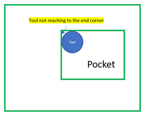
For example, an end mill with 0.5 inch diameter can create a 0.25 inch corner radius. However, a lower radius will be impossible because of inaccessible corner geometry.
If one decides to stick to such a pocket design, it will require extra money and time. For that, we will need a different process or operation to create sharp corners, say EDM sinker. If the pocket is through, wire cut EDM can be the solution.
Such a design can also lead to operational failure because of stress concentration near sharp corners.
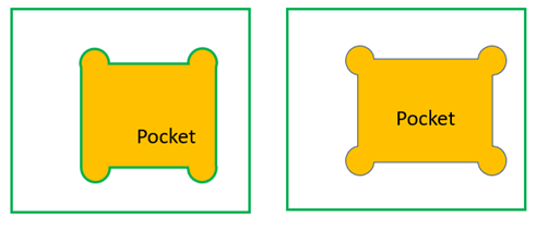
The solution could be one-sided or two-sided overshot, as shown in Figure 3 . It is simply like extending corners beyond pocket boundaries. So, the functional requirement of inserting rectangular counter male part gets easily satisfied. Also, machining this kind of pocket is practical and easy.
We can save many manufacturing dollars without compromising functionality if we know of such pitfalls and potential solutions at an early design stage.
Now let’s take a case where we can avoid sharp corners and have round corner pockets. The question that arises is, what should be the minimum corner radius?
2. Milling a pocket with a deep side radius:
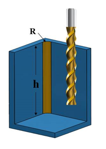
Consider a pocket 50 mm deep and having a tight corner radius of 3 mm. To make this corner, a 6 mm diameter end mill cutter will be helpful. Looking at manufacturing feasibility, end mills work best when they are rigid.
Since the Pocket height to diameter ratio is above 4, it will be progressively more complex and time-consuming. In such a case, milling can be done with a step-down approach with small increments. Also, to avoid tool breakage, the machinist will have to reduce tool feed. This will increase the machining time and, ultimately, the feature cost.
It is evident that the bigger the pocket corner radius, the bigger the diameter and faster the tool action, which lowers the manufacturing time and cost. The thumb rule is that the end mill can cut easily if the pocket depth is less than 8 times the corner radius.
So the designer needs to avoid these deep corner pockets with a H/D ratio of more than 4. There could be a workaround like precisely drilling those deep corners with twist drills and then milling using a rough end mill that is 2 times greater than the required finish radius corner. After rough milling, the corner radius and the step-over created due to the rough and finish end mill will be machined.
In this case, the machining time will be reduced compared to the end mill with slow feed.
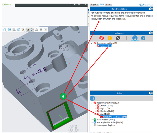
3. Pocket with fillet on top edges:
Functional requirements for fillets can be avoiding sharp corners, avoiding accidents while handling parts, having better stress flow, or looking aesthetic. For internal edges, fillets are concave and convex for external edges. We are taking a case of external fillets since internal fillets called corner radii can be machined easily with end mill cutters. Bottom radii can be obtained using ball-nose or hog-nose tools. An extra round corner tool will be needed to machine an external fillet, as shown in Figure 5. This will increase machining time and feature cost.
If the aesthetic look is not important and edges are not interfering while handling, these edges can be manufactured without fillets or replaced by simple chamfers. Unlike fillets, which require different size tools as per the fillet radius, chamfers need only one size tool for different sizes.

Manufacturing such fillets is costlier but fillets are the better option for preventing rusting compared to chamfers. This is because fillets allow uniform distribution of coatings or paint compared to edges of chamfers. Also, fillets are suitable for uniform stress distribution on the edges of the part.
Looking at the pros and cons, designers should decide whether they need to have a fillet in the design or not. Such decisions are easier when brought to the notice of the designer at an early stage. Late stage design changes are costly and complicated.
4. Hole with tolerances:
Consider two holes on a part. Both are similar, with the only difference of tolerance of +-0.01 mm added on one hole.
As a simple case, it is obvious that a hole without tolerance will need only drilling, and a hole with tolerance will need reaming operation after drilling. It is obvious that feature cost increases due to the since an extra operation is needed.
The functional requirement of a tight tolerance on a hole is to have a perfect hole fit. However, the designer can decide whether it is indeed the case.
It is essential to analyze the “design for manufacturing” feasibility for every feature meticulously. Though more time may be required for product development at the design stage, it will prevent the cascading effect of higher cost in the latter stages, due to engineering changes after the production stage of the product or higher inbuilt cost of the final product. Can we help designers consider such aspects without spending too much time?
DFMPro to the rescue:
Suppose the designer gives time to analyze and optimize the design considering manufacturing feasibility alternate manufacturing process without affecting core functionality of the part. It will save the rework during manufacturing and save cost.
How can we reduce the designer’s time for evaluating the design with a 360-degree view? There could be several features, simple to complex parts, and many design rules that take time and make the designer work hard.
This is where DFMPro provides the right assistance at the right time. It validates the part design from manufacturing and other perspectives and provides a platform for the team or organization where all the stakeholders can be in sync on the best practices.
Let’s revisit the cases discussed above and see how DFMPro helps designers identify where design can be improved.
Consider the first design rule for sharp corners in a pocket. DFMPro first recognizes all the details associated with the 3D model, such as type of feature, feature details such as sharp corners, pocket physical dimensions, etc. Post analysis, the results are displayed for the whole part. Refer Figure 6.
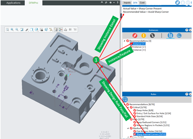
As we can see, the output “Rules” widget shows that the “Sharp Internal corners” rule has failedalong with the feature and above widget showing the reason for failure.
This is how DFMPro qualifies the design for the pocket with sharp internal corners. Now imagine if it also quantifies the directional increase in cost. Is it possible?
The answer is yes. DFMPro also has the Cost add-on module along with DFM results. The Cost add-on tab provides all the details related to manufacturing the part, such as Material Cost, Process Cost, Total Cost, Individual Feature Cost, Set-ups, etc.
Apart from that, it gives Cost insights such as Potential Cost-saving, Quick indicators such as Target Cost, and Previous run Cost.
Many factors depend on cost optimization, such as supplier selection, complex supply chain activities, cost negotiation, workforce productivity, economic material procurement, etc. Based on this, the final cost arrives. But before all these considerations, the design has to be optimized to arrive at a “good design” state. If the design is not optimized correctly, we are likely to optimize cost for an incorrect design. With this consideration, DFMPro is streamlined for design optimization and proposed directional cost which is more important for a design engineer. Hence this cost may not match a “Should-cost”, which depends on many complex supply chain activities.
All the required cost inputs such as Machine hour rate, set-up time, Machine allocation to the part, Process mapping, cost models are configurable.
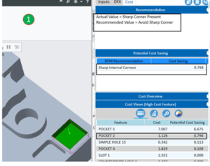
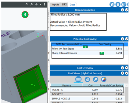
DFMPro alerts the designer that the pocket has sharp corners which impacts manufacturing feasibility. Additionally, it gives the designer a sense of how much it can affect the manufacturing cost. This is shown by the cost-insight function like Potential Cost Saving. As shown in Figure 7, after clicking on Pocket2, DFMPro highlights the feature and displays the total feature cost, and potential cost savings if the designer avoids sharp corners. It also shows the reason for potential costs and recommendations. The feature cost is higher because of added EDM cost due to sharp corners, which are not possible by milling cutters.
Similarly, we are also getting results for the other 3 design rules.
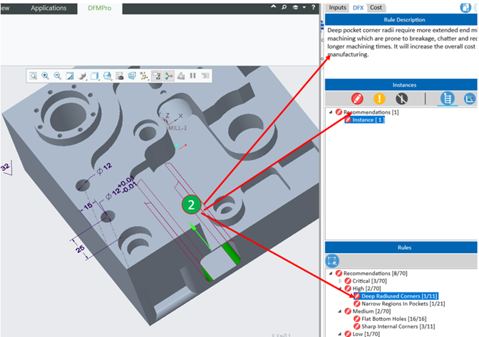
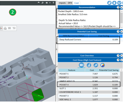
Milling a pocket with a deep side radius:
Pocket with fillet on top edges:
DFMPro shows potential cost savings for a feature for multiple design rules. For example, the following figure suggests avoiding sharp corners and fillets on top edges. It shows potential cost savings for both design rules in Feature Cost Widget and separately in Potential Cost Saving Widget.
Hole with tolerances:
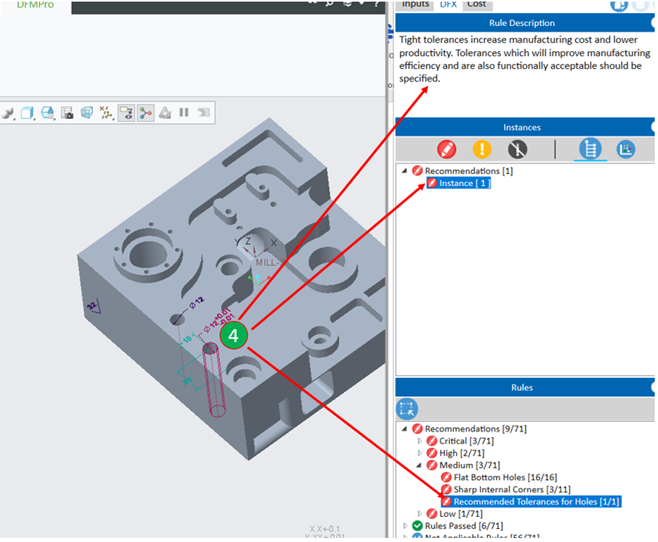
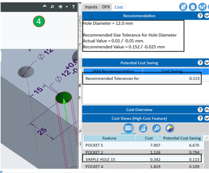
Similarly, the designer can benefit from DFM as well as cost feedback for a tightly tolerance hole.
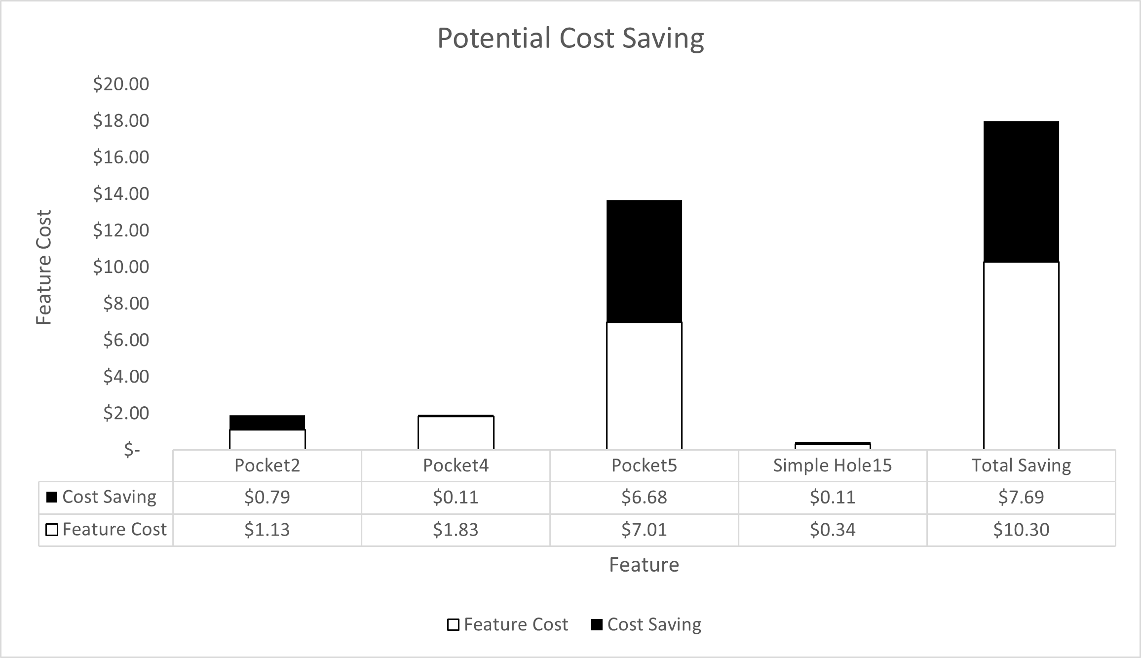
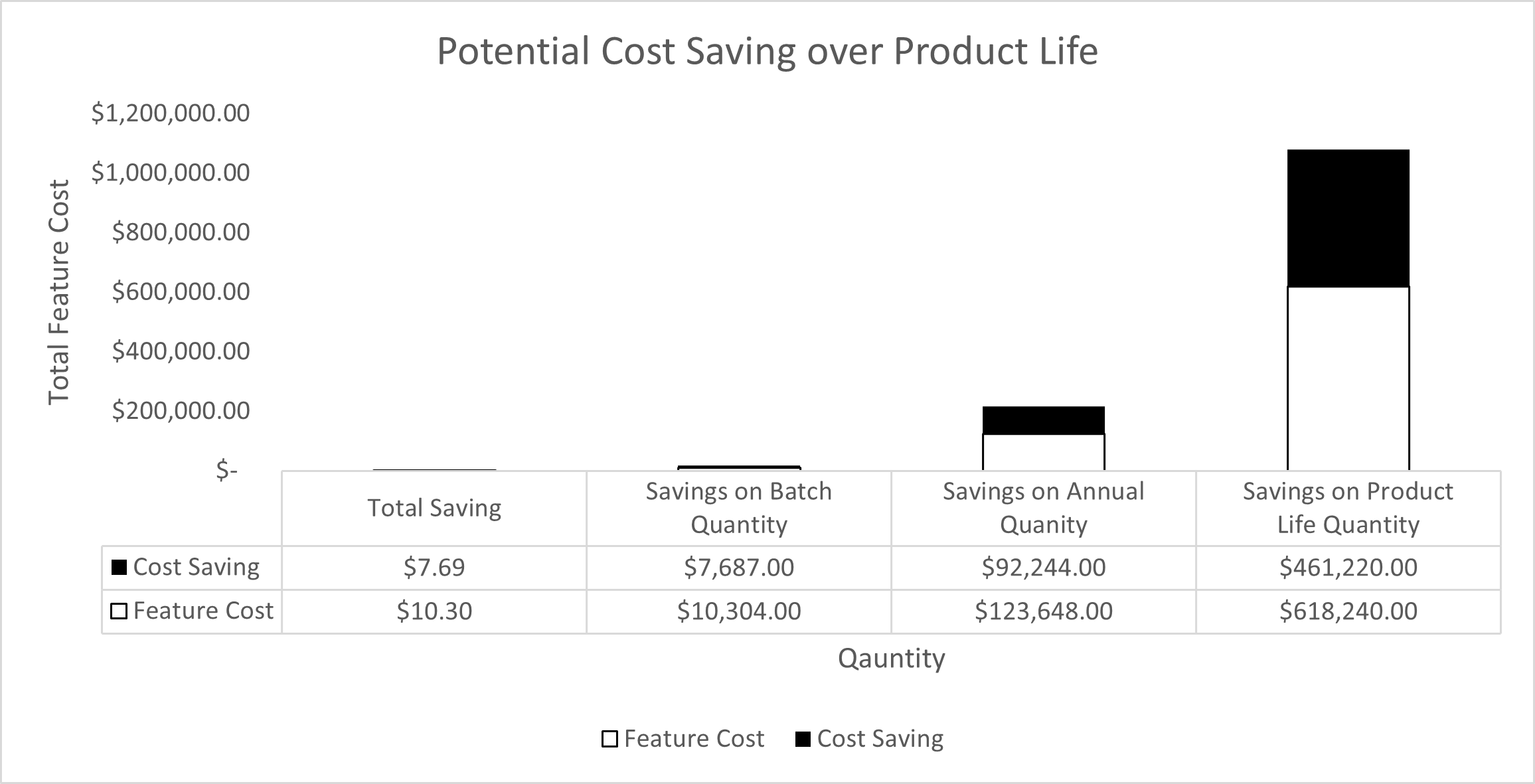
As we can see, there could be a possibility for design improvement and cost-saving potential. As shown below (Figure 14, Figure 15, Figure 16), the designer can realize multiple potential gains:
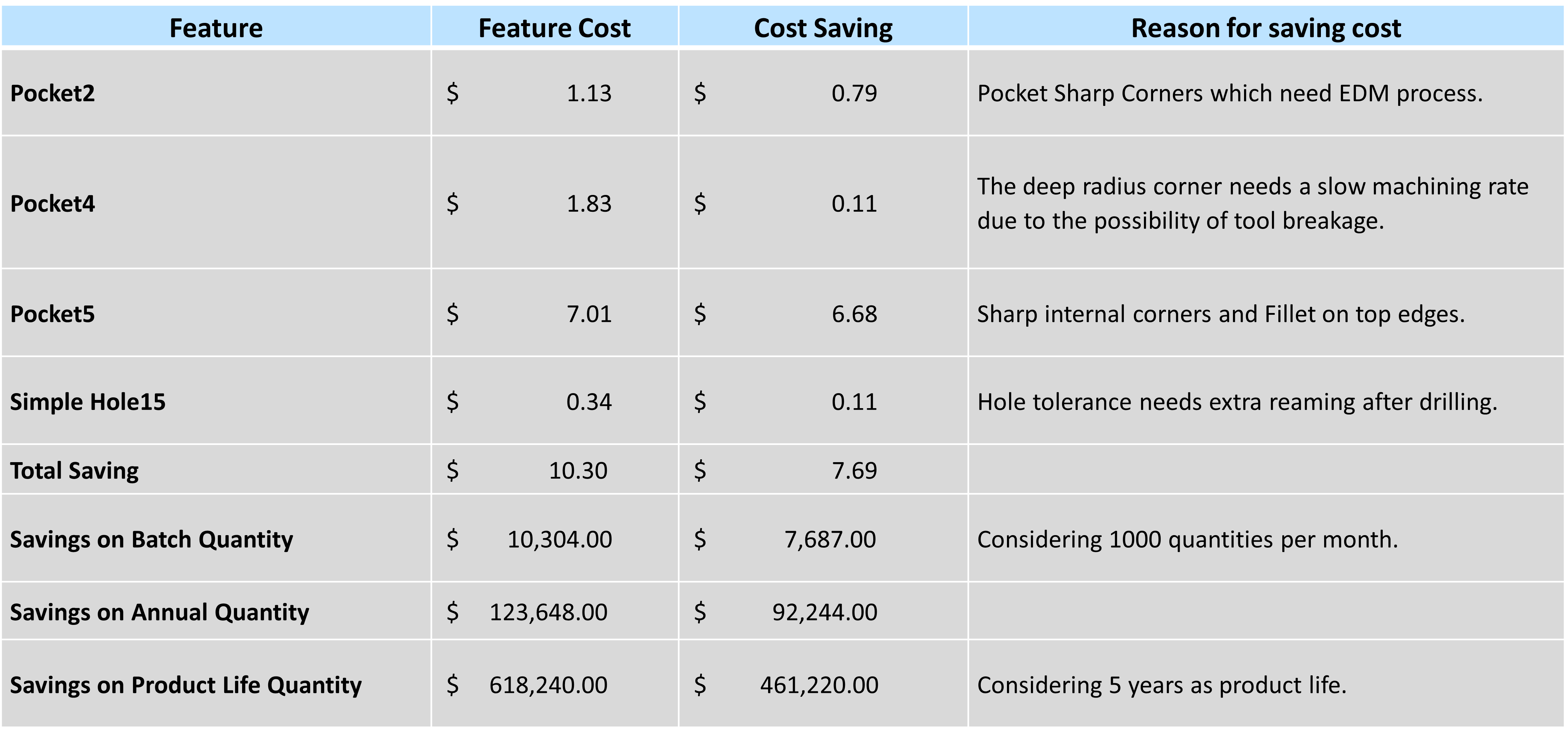
Whether these design changes are acceptable given the function of the part is for the designer to decide. If in doubt, a discussion can be had with peers, senior designers and manufacturing experts. DFMPro helps highlight these observations at an early stage where they can be easily acted on saving time and money for the organization.
Conclusion:
It is necessary and beneficial to invest more time in optimizing the design, which can satisfy all the functionality, budget, and physical properties by considering the manufacturing feasibility and cost.
DFMPro helps focus on a holistic design approach and assists designers in utilizing the saved time to improve design, find alternate methods, etc. Using DFMPro along with other simulation tools and capturing learnings from the simulation as best practices helps reduce design iterations required for optimization. Apart from that, it helps train new design engineers on various manufacturing process details and helps improve manufacturing cost literacy.