PTC has introduced multibody modeling one of the essential enhancements in Creo Parametric 7.0 and above.
Overview of Multibody Modeling:
Before introducing multibody functionality in Creo parametric, if two features or their geometry intersected, these intersected geometry volumes were merging with each other. In the case of complex casting design, for creating interior cavity portion, designers create it in the surfaces and later merge all surfaces into a single surface. While converting those interior surfaces into solid, they removed them from the solid exterior geometry that creates internal casting cavities, as shown in Figure 1. It was a very time consuming activity to create geometry with the surface, merge it as one surface, and then remove it from outer geometry. Designers used to spend maximum time to get this done. Now with new multibody functionality, it would be a much easier task. Designers can create two separate bodies for interior & exterior geometry, easily remove one body from another with a Boolean operation & save time. Another good point about multibody is assigning different materials and defining their corresponding parameters which later can be consumed in drawings. In case of assembly design, multibody functionality can be used effectively to create an assembly in a part environment. Subsequently, one can extract each body as separate components and create an assembly with the associated linkage between body and part. No extra assembly constraints are required. Multibody modeling simplifies part and assembly design.
Figure 1
Benefits:
- Skeletons can contain multiple bodies.
- Copy geometry, merge, and publish geometry can be used to maintain associativity.
- Fast conceptualized assembly models can be created easily in the part environment with correct references, and later individual bodies can be extracted into separate part files.
- Allows to merge or subtract one body from another body.
- Assign separate materials to the individual body, which helps weight calculations.
- Separate CAD parameters can be assigned for each body.
- Multi-material functionality will help to design a multi-shot injection molding parts.
In Creo Parametric 7.0 and above version, when opening an old version part or while creating a new part, you can view “Body1” in the CAD model tree, as shown in Figure 2
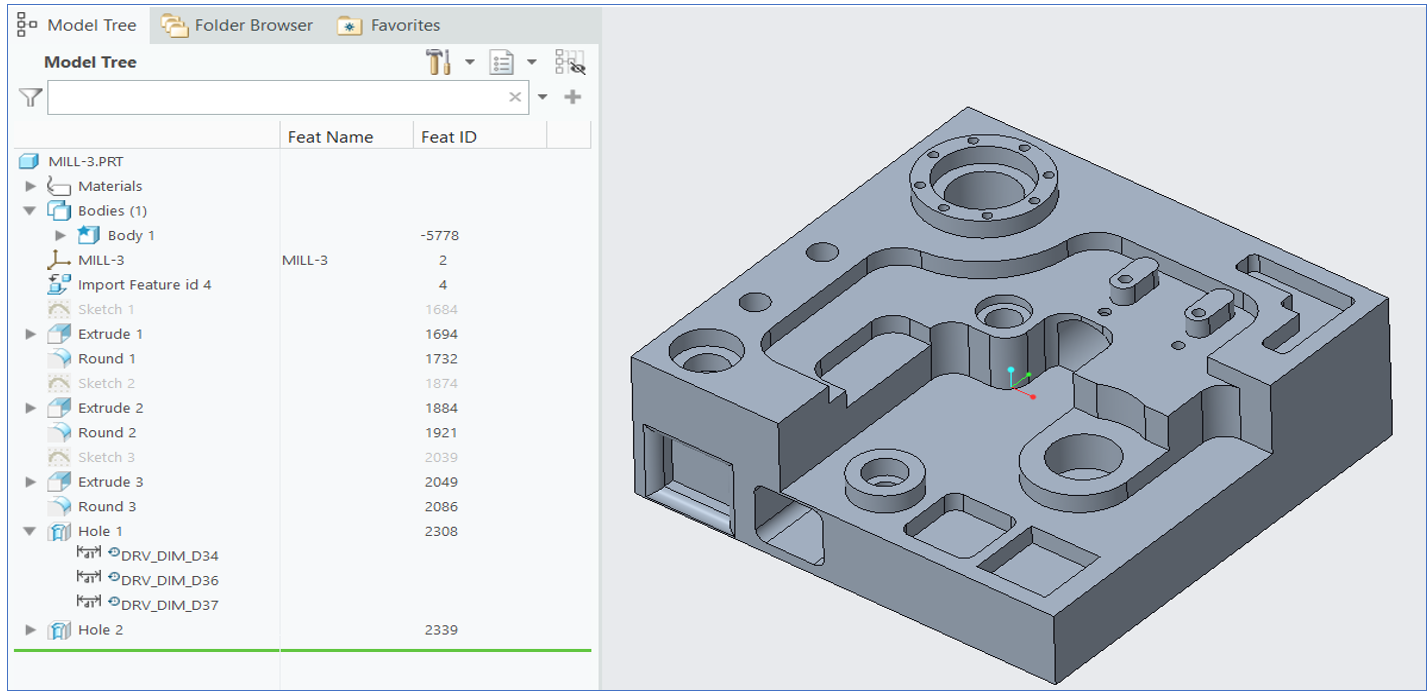
Figure 2
Now let’s take a few multibody cases and see how DFMPro handles them.
Mark is a design engineer and is familiar with DFMPro software. He is now using multibody functionality to create sheet-metal parts with PEM nuts in a single design. He created a sheet metal bracket as body 1 and added a few sheet metal features like holes, cutouts, etc. Now he added a new body for hardware like PEM nuts. So, part contains multiple bodies, one of sheet metal and others are hardware, as shown in Figure 3. He ran DFMPro analysis by using sheet metal as a manufacturing process. While running analysis, DFMPro smartly identified the sheet metal body and provides related DFM recommendations. For example, it detects the cutout issue, which is very near the part edge, as shown in Figure 4.
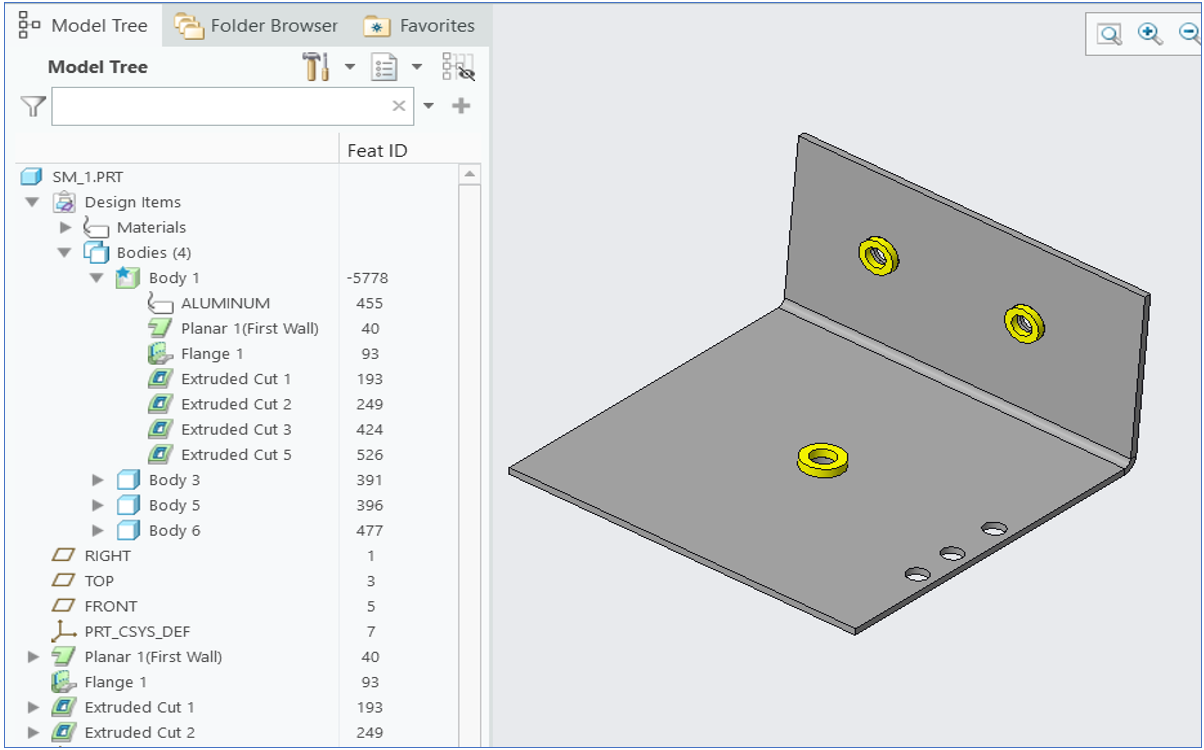
Figure 3
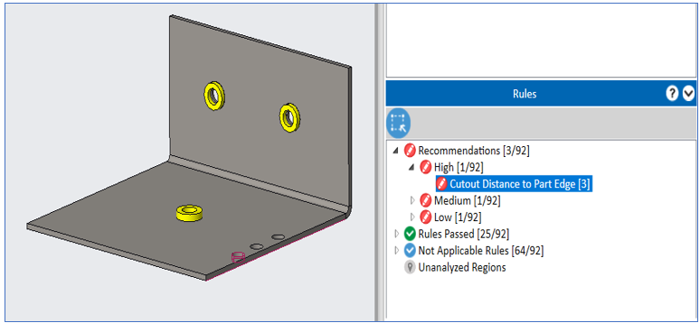
Figure 4
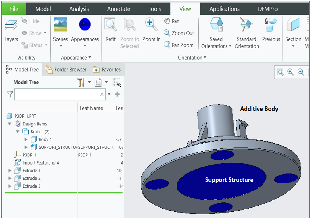
Figure 5
Figure 6
Next, Mark also used the multi-body functionality for designing parts manufactured using insert-molding and over-molding. Before reviewing the DFMPro analysis for such designs, let’s have a quick overview of insert molding and over-molding.
Insert molding: Insert injection molding is the process of molding or forming plastic parts around other, non-plastic parts like inserts. Inserts are typically metal parts that are used to reinforce the mechanical properties of plastic parts. The inserts are placed into the mold, and thermoplastic is injected into the mold to form the part. It is commonly used in various industries, including medical, automotive, consumer products, and electronic components. Common applications include electronic housings, knobs, dials, hand-held devices, etc.
Overmolding: It is a multi-step injection molding process where two or more components are molded over top of one another. It is called two-shot molding because it is a two-step process. It reduces production time because the second piece is molded directly onto the first part rather than manufacturing the two pieces separately and then assembling them.
Figure 7 shows a case of insert molding where a plastic part is created as one body & inserts are added in the separate bodies. When Mark executed DFMPro by selecting “Injection Molding” as the process, DFMPro smartly identified the plastic body based on assigned body material & excluded inserts from the analysis. Figure 7 shows DFMPro shows recommendations only for plastic body & not inserts.

Figure 7
Figure 8 shows an over-molding case with one blue-colored body over-molded over the other. When Mark ran the analysis based on assigned material to the body, DFMPro analyzed these two bodies separately as individual plastic parts and provided corresponding design recommendations for each one.
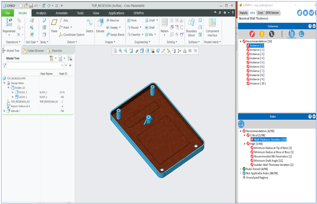
Figure 8
DFMPro for Creo Parametric supports these multi-body use cases starting from v9.3 (refer related Release Notes for more details). Creo Parametric designers can now freely design such parts using multi-body functionality and DFMPro will analyze the right bodies as per the use case. In forthcoming releases, DFMPro will support more use cases so that customers and designers can adopt the multi-body functionality in Creo Parametric and continue to analyze those designs in DFMPro. In an upcoming blog, we will discuss about additional use cases as DFMPro continues adding related support in the software.
DFMPro for Creo Parametric is a CAD integrated DFM software. It helps designers check their designs for manufacturability and assembly and correct these problems early in the design stage. It helps automate the iterative design process via a series of rule-based checks, identifying design areas that are difficult, expensive, or impossible to manufacture which would otherwise lead to manufacturing, assembly and quality issues. It helps the organization improve engineering efficiency by minimizing rework and engineering changes (ECOs).