
Plastic Material Selection – It’s A Jungle Out There!
Part 1 Understanding Plastic Materials
David Wright in his book “Failure of Plastics and Rubber Products” divides the failures of plastic into categories and percentages as illustrated in Figure 1.
![Figure 1 - Human Causes of Plastics Failures [1]](https://d38kgjogivm3r3.cloudfront.net/wp-content/uploads/2017/07/Figure-1-Human-Causes-of-Plastics-Failures-1.png) Figure 1 – Human Causes of Plastics Failures [1]
Figure 1 – Human Causes of Plastics Failures [1]
As we see, almost half of the failures is contributed by poor understanding and selection of materials. Based on this observation it can be concluded that a better understanding and choice of material would definitely eliminate half of the failures.
How do we select the right material? There are about 100,000 different types, brands, and grades of plastics to choose from.
There is a material jungle out there!
The first step towards achieving this is to understand the basics of plastic materials.
Once we have understood the basics, the second step is to systematically boil it down to less than a handful of candidate materials.
Let us start with the basics of polymers which constitute 90 percent or more of material we call “plastic”.
Poly-mer:
many “mers”
Mer: Derived from the Greek word meros, meaning a part or unit, a mer is the repeating structural unit of any polymer. One mer is a monomer, two mers form a dimer, three – a trimer, four -a tetramer and so forth. A great many mers form a polymer.
The polymer starts with the monomer which will form the mer or main component of the polymer.
Figure 2 illustrates the ethylene monomer used to create polyethylene.
 Figure 2 – Ethylene Monomer [2]
The double bond of the monomer is broken and long chains which is formed through a process called polymerization.
Multiple chains in their relaxed state entangle as shown in Figure 3.
![Figure 3 - Entangled Polyethylene Chains [2]](https://d38kgjogivm3r3.cloudfront.net/wp-content/uploads/2017/07/Figure-3-Entangled-Polyethylene-Chains-2.jpg) Figure 3 – Entangled Polyethylene Chains [2]
Figure 3 – Entangled Polyethylene Chains [2]
Depending upon mobility and chain conformation the morphology could be amorphous or have areas of order (semi crystalline) as shown in Figure 4.
 |  |
Figure 4 – Amorphous (left) and Semi crystalline (right) Polymers
“Plastic” is actually a compound of some form of polymeric material with various additives.
Additives, such as
- Antioxidants
- Fillers
- Colorants
- Plasticizers
- Flame retardants…
..which combined with a base polymer makes up what commonly is termed as “Plastic.” Although the additives alter the performance of the plastic material, the polymer itself is the most important component.
Figure 5. shows the overall plastic family.
 Figure 5 – The Overall Plastic Family
In the case of thermoplastics, melting and solidifying are physical changes and reversible. As an example, ice can be melted into water by adding heat and refrozen by removing heat.
In thermosets, melting and solidifying are chemical changes (cross linking) and are non-reversible. Burning hydrogen (H2) in air (O2) will result in water (H2O), a chemical change that cannot be reversed by heating or cooling.
Figure 6. shows the difference in the bonds in thermoplastic and thermoset chains.
The disassociation energy of covalent bonds >>> secondary bonds.
In the case of thermoplastics, by supplying enough heat energy, the secondary bonds can be overcome and the chains start to slide.
However, in the case of thermosets, adding heat will not overcome the covalent bonds in both directions. Continuing to heat will make them burn but not slide.
 |  |
Figure 6 – Thermoplastic (left) and Thermosetting (right) Structures
The rest of the article will be devoted primarily to thermoplastics.
The Thermoplastic Family
Figure 7. shows different types of polymers in the thermoplastic family(Also refer figure 4).
 Figure 7 – Different Types of Thermoplastic
This family can be divided into:
Amorphous
Some major characteristics of this family are:
- No fixed melting point
- Have a range of temperature where the chains start to slide. Further,increase in temperature can facilitate plastic flow.
- In many instances can be transparent
- Generally, have lower tensile strength and higher impact strength
- Much lower and very predictable shrinkage
- Uniform shrinkage in all directions
Common examples of amorphous plastics are Polycarbonates (PC), Acrylic – Polymethyl methacrylate (PMMA), Polystyrenes (PS), etc.
Semi Crystalline
Main characteristics of this family are:
- These materials show higher densities as result of close packing structure
- These polymers show better chemical resistance, higher tensile strength, better creep
resistance and greater stability at a higher temperature
- They have a sharp melting point called Tm,
the point where the crystalline areas open up to create an amorphous state.
- They are generallynon-transparent
- They exhibit higher shrinkage
- They have different shrinkage in flow and cross flow direction and therefore, more susceptible to warpage
Common examples of semi-crystalline plastics are Nylons, Polyethylene, Polypropylenes, etc.
There are also special and (,or) combination materials ,for instance, most TPEs (thermoplastic elastomers).
Note that almost all materials are amorphous at injection. (One exception is LCPs – Liquid Crystal Polymers – that form areas of highly ordered structures even in the liquid phase).
Figure 8. shows the overall thermoplastic family ranging from commodity plastics such as PS (polystyrene) on the amorphous side and PE (polyethylene) on the semi crystalline side to very high heat materials such as PEI (polyetherimide) and PEEK (polyetheretherketone) on the corresponding side.
The main (and perhaps the only) distinguisher from the low end to the high end is the continuous use of temperature ranging from sub 100 deg C to over 500 deg C.
Note that this hierarchy is NOT based on mechanical properties. Indeed, some of the materials on the bottom, may have higher tensile strength and toughness than the ones on the top.
 Figure 8 – The Overall Thermoplastic Family
Molecular Weight
- What is it?
- Why is it important in plastics?
- How is it measured?
One monomer of polystyrene has a molecular weight of 104 (see figure 9).
Carbon has an atomic weight of 12. Hydrogen has an atomic weight of 1.
Therefore, C8H8 = (12 x 8) + (1 x 8) = 104
 Figure 9 – Polystyrene Monomer
Look at figure 10. The more times a repeat in a polymer, the longer the polymer chain, and the higher the molecular weight. The final molecular weight is known as the AMW or Average Molecular Weight of the polymer.
 Figure 10 – Polystyrene Chain
A part made from long polymer chains (or higher AMW) is stronger than one made from short polymer chains (or lower AWM) because the molecules get tangled together more. See figure 11.
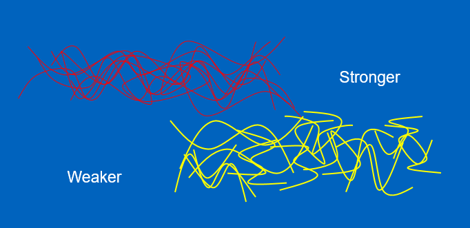 Figure 11 – Long and Short Chains
Polyethylene AMW (Average Molecular Weight) can range from about
- ~ 200-600 (as candle wax)
- ~ 10,000 (LDPE-HDPE, low density polyethylene, high density polyethylene) – milk jugs, food containers
- 1 – 5.67 million (UHMWPE – ultra-high molecular weight polyethylene) – competes with Aramid in bulletproof vests
See figure 12.
 |  | |
 | ||
 |  |  |
Figure 12 – Effect of AMW on the Properties of Polyethyline
Thermoplastics and Viscosity
Determining the viscosity of various plastic is very important in determination of a part with a certain wall thickness and length which will fill with practical molding pressures. The most common method to measure this is the Melt Flow Rate (MFR) or Melt Flow Index (MFI). This is measured by ASTM D1238 and is the flow in grams of a material in 10 minutes through an orifice 0.0825 in diameter under a certain force and at a certain temperature. Figure (no.13)
In the case of PC (polycarbonate), the force is 1.2 kg and the temperature is 300 deg C.
Lower the MFR, ower the flow; higher the AMW, higher the viscosity and higher the strength.
 Figure 13 – A Typical MFR Measuring Machine
It is a common mistake to use the MFR or MFI index to compare the flow of two different materials during molding. We assume that higher MFR means higher flow and therefore, lower viscosity.
The issue is that the MFI is measured at very low shear rates and molding occurs at very high ones.
Common Polymer Manufacturing Processes
Addition Polymers
Manufactured by process called chain polymerization as they are formed by a chain reaction.
- Single unit is added at a time.
- The repeating unit has same chemical formula as the monomer.
X in the formula is substituted with various molecules to form different polymers.
See figure 14.
 |
 |
Figure 14 Addition Polymers [3]
Condensation Polymers
Unlike addition polymers, these polymers are formed by combining two different chemicals through giving up a molecule (mostly water) in the process. Figure 16. shows the reaction for polycarbonate. Bisphenol A is reacted with Carbonic Acid. The process the BPA gives up the Hydroxyl group and the Carbonic Acid a Hydrogen atom, creating a molecule of H2O (water) – hence the term condensation. This reaction is allowed to continue until the required AMW is obtained (about 50,000 in this case).
Condensation polymers require thorough drying with DRIED air at a controlled dew point, heated to a certain temperature and for a certain range of time.
In the case of PC these parameters are:
If the material is not dried (or,not dried properly), the moisture that is attached to the plastic pellets would react with the polymer chains under high temperature splitting them in half. One molecule of water can reduce the molecular weight of one chain of PC from 50,000 to 25,000. This will seriously impact the physical properties of the part and inconsistencies in the molding process.
 Figure 15 Condensation Polymer (Polycarbonate in This Example)
To be followed by article on a systematic method of selecting the most optimum half a dozen or so materials from the thousands available in the plastics jungle.
References:
[1] David Wright, “Failure of Plastics and Rubber Products “
[2] Courtesy Joseph P McFadden
[3] Courtesy Mukund Patankar