DFMPro for Injection Molding
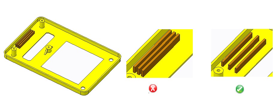
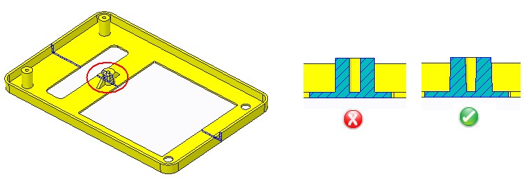
Mold Wall Thickness
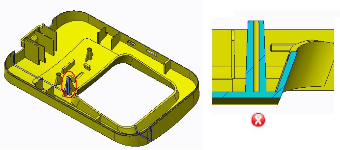
The thickness of the mold wall depends on the spacing between various features in the plastic model. If features like ribs, bosses are placed close to each other or the walls of the parts, thin areas are created which can be hard to cool and can affect quality. If the mold wall is too thin, it is also difficult to manufacture and can also result in a lower life for the mold due to problems like hot blade creation and differential cooling. Minimum allowable mold wall thickness needs to be decided based on process and material considerations.
Uniform Wall Thickness
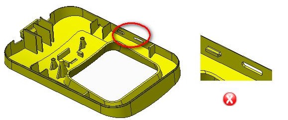
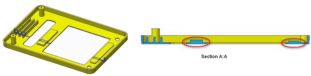 Non-uniform wall sections can contribute to warpage and stresses in molded parts. Sections which are too thin have a higher chance of breakage in handling, may restrict the flow of material and may trap air causing a defective part. Too heavy a wall thickness, on the other hand, will slow the curing cycle and add to material cost and increase cycle time.
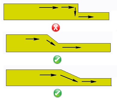
Generally, thinner walls are more feasible with small parts rather than with large ones. The limiting factor in wall thinness is the tendency for the plastic material in thin walls to cool and solidify before the mold is filled. The shorter the material flow, the thinner the wall can be. Walls also should be as uniform in thickness as possible to avoid warpage from uneven shrinkage. When changes in wall thickness are unavoidable, the transition should be gradual and not abrupt.
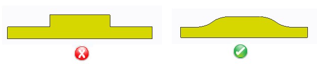
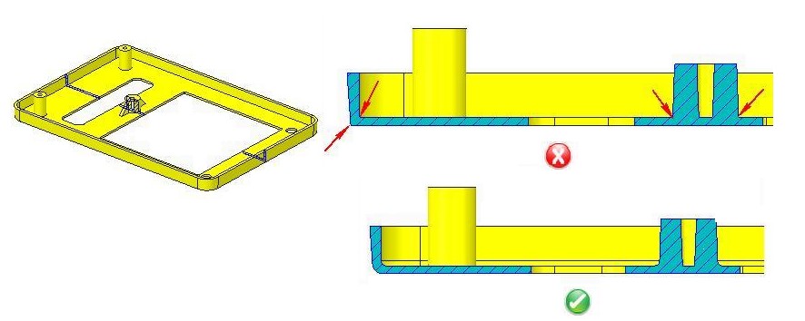
Wall thickness variation should be within tolerance so as to allow for smooth filling of the mold. Ideally, the wall thickness should be uniform throughout the part (equal to the nominal wall thickness). In reality, the variation is unavoidable due to requirements of functions and aesthetics. However, the amount of variation has to be minimized.
 Non-uniform wall thicknesses may cause uneven plastic flow and cause different parts of the part to cool at different rates. This can cause warpage toward the heavier portion of the model. If an uneven wall thickness is unavoidable, it may be necessary to provide additional cooling for the heavier sections. This increases tooling complexity and adds to production costs. In general, gradual change of 25% and 15% is acceptable in amorphous (PC, ABS, etc.) and semi crystalline (Nylons, PE, etc.) materials respectively.
 Draft angle design is an important factor when designing plastic parts. Because of shrinkage of plastic material, injection molded parts have a tendency to shrink onto a core. This creates higher contact pressure on the core surface and increases friction between the core and the part, thus making ejection of the part from the mold difficult. Hence, draft angles should be designed properly to assist in part ejection. This also reduces cycle time and improves productivity. Draft angles should be used on interior and exterior walls of the part along the pulling direction. It is typically recommended that the draft angle for sidewall should be at least between 0.5 to 2 degrees for inside and outside walls, although a larger angle will make it easier for part release.
Undercuts should be avoided for ease of manufacturing. Undercuts typically require additional mechanisms for manufacture adding to mold cost and complexity. In addition, the part must have room to flex and deform. Clever part design or minor design concessions often can eliminate complex mechanisms for undercuts. Undercuts may require additional time for unloading molds. It is recommended that undercuts on a part should be avoided to the extent possible.
Generously rounded corners provide a number of advantages. There is less stress concentration on the part and on the tool. Because of sharp corners, material flow is not smooth and tends to be difficult to fill, reduces tooling strength and causes stress concentration. Parts with radii and fillets are more economical and easier to produce, reduce chipping, simplify mold construction and add strength to molded part with good appearance.
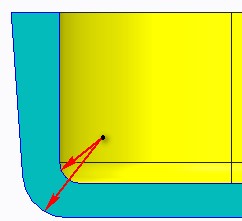 General design guideline suggests that corner radii should be at least one-half the wall thickness. It is recommended to avoid sharp corners and use generous fillets and radii whenever required.
In addition inside and outside radii should have same center so as to avoid stresses during cooling as shown in the image.
Core pins are used to produce holes in plastic parts. Through holes are easier to produce than blind holes which don’t go through the entire part. Blind holes are created by pins that are supported at only one end; hence such pins should not be long. Longer pins will deflect more and be pushed by the pressure of the molten plastic material during molding. It is recommended that hole depth-to-diameter ratio should not be more than 2.