In the course of reading about sheet metal design guidelines by Gerald Davis, I gained an insight into real shop floor issues which can be side-stepped by correctly designing sheet metal parts.
Few simple yet integral tips which need to be taken into consideration while designing a sheet metal part are-
Minimum Hole Diameter
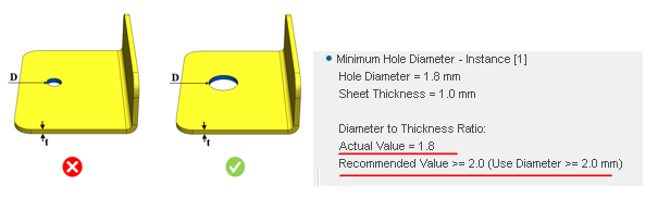
Holes are a commonly used feature in a sheet metal part. Small holes in sheet metal can be punched or can be laser cut, depending on the equipment used for punching. As general guideline suggests , hole diameter equal to sheet thickness can be punched. If the hole diameter is too small, then chances of punch breaking or bending during operation is high.
In line with this design tip, an integral check is available in DFMPro namely Minimum Hole Diameter where the software identifies the minimum hole diameter and computes the diameter to sheet thickness ratio.
The default configuration in DFMPro suggests minimum hole diameter to sheet thickness ratio to be >=2.0
Minimum Bend Radius
Minimum bend radius is a critical parameter which depends on both material and process used to produce the bend.
 More the ductility of the material, smaller the bend radius which can be achieved. The guideline suggests that the inside bend radius should be at least equal to the sheet thickness. Preferably, the inside bend radius should be 2 times sheet thickness.
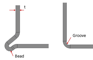
Stiffer materials, like 6061 or Aluminum2014, 2024, might require a ratio of four to eight times the sheet thickness. Small bend radius can be achieved by adding a bead or forming a groove. For sheet thickness up to 0.8 mm, an external bead can be used & for a sheet thickness over 0.8 mm, formed groove one-third to one-half the sheet thickness can be used.
Considering this, user can avail the Minimum Bend Radius rule in DFMPro. This check computes inside bend radius and checks the ratio of bend radius to sheet thickness. User can configure the ratio based on the material.
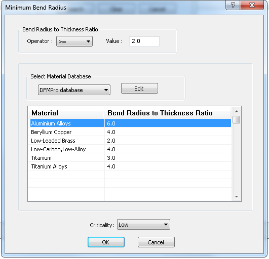
Ratios are configured for the hard material condition
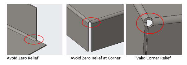
Bend Relief
When sheet metal makes a transition from a bend to a flat surface, or to another bend, it tends to tear depending on the geometry of the boundary. As a general practice, relief is provided to the flange for ease of bending operation.
Benefits of Bend Relief
- Makes bend easier to produce,
- Eliminates burrs and sharp points,
- Reduces fracture propagation if the part is subjected to vibration, and
- Part will be stronger and more stable.
A similar check is available in DFMPro –Bend Relief – to identify parameters of bend relief & validate with preconfigured values. As a general guidelines suggest , the relief width (W) to the sheet thickness ratio should be >1.5 & relief depth (D) should be >= t + R.
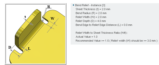
t= Sheet Thickness
R= Bend Radius
W= Bend Relief Width
D= Bend Relief Depth
L= Bend Edge to Relief Edge Distance
Hole distance to bend
Hole distortion near the bend- A hole that is punched near the bend line may turn into an unintended bend relief. If hole’s close to bend line, it would be susceptible to distortion. To minimize hole distortion near to bend, minimum distance should be maintained between holes & bends.
The Hole distance to bend rule in DFMPro checks the ratio of hole distance to sheet thickness and validates with a preconfigured value.
The design essentials gathered after observing downstream shop floor issues listed in the article are directly addressed by DFMPro, right at the stage of design.
Need to know more about ways to address real shop floor issues? Stay tuned!