UL Certification and Why It Is Important to Plastics Part Designers!
UL certification or UL Safety certification is the process of assessing the compliance of products to recognized safety requirements. This certification most frequently addresses electrical and mechanical safety, fire risks and other product hazards and can include the assessment of other attributes, all focused on making products safer to use. [1]
In a majority of cases, this certification is optional for manufacturers – as opposed to the mandatory requirements such as Federal Motor Vehicle Safety Standards (FMVSS) for the safety of automobiles.
However, this is a choice most major manufacturers make to validate the safety of their products as well as to assure the customer that the product has been tested to the rigorous standards of safety established by UL. This also improves the competitive advantage of the products.
Main Areas of Safety Related Plastic Materials and Design
Fire
Prevent Spread of fire originating within equipment. This can be due to
- Electrical overload
- Component failure
- Insulation breakdown
- Loose connections
Energy and Related
Injury or fire may result from a short circuit between adjacent poles of high current supplies – burns caused due to contact with hot accessible parts or high capacitance circuits.
Electrical
Prevent human contact with hazardous voltage. This includes:
- Being able to touch a component carrying this voltage through an opening in the enclosure
- Exposure to such voltages as a result of the failure of the enclosure
- Steady state voltages up to 42,4 V peak, or 60 V DC are not generally regarded as hazardous under dry conditions for an area of contact equivalent to a human hand. Bare parts which have to be touched or handled should be at earth potential or properly insulated.
Mechanical
Enclosures must have adequate mechanical strength and should be constructed as to remain safe in the meeting of this standard when subjected to handling as may be expected. This includes:
- Not being able to access a hazard such as a moving gear, sharp edges, etc.
- Exposure to these hazards as a result of the failure of the enclosure
Safety Standards
As of the writing of this article there are 1,021 safety standards for various types of equipment. See figure 1.
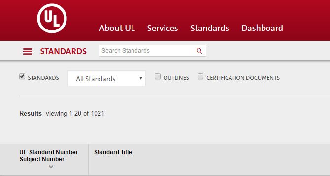
Figure 1 UL Standards Listing
Some the familiar ones out of these may be:
- UL 94 – Standard for Tests for Flammability of Plastic Materials for Parts in Devices and Appliances
- UL 923 – Standard for Microwave Cooking Appliances
- UL 1026 – Standard for Household Electric Cooking and Food Serving Appliances
- IEC60601-1 – Safety of Medical Electrical Equipment
- UL 60950-1 – Information Technology Equipment Safety
For the purpose of this article, we will concentrate on:
- UL 94 – a standard that all plastic part designers need to be familiar with, and
- UL 60950-1 Information Technology Equipment Safety, which I am most familiar with and is a typical standard a vast number designers may need to be comply with.
Note: This article touches most (but not necessarily all) requirements for plastic part material and design requirements related to UL 60950-1. In my experience meeting UL requirements may sometimes be in conflict with recommended plastic part design practices.
It is highly recommended that one consult with a UL expert before finalizing the design.
UL 94
UL 94 evaluates the flammability of polymeric (plastic) materials, used for parts in devices and appliances in response to a small, open flame or radiant heat source under controlled laboratory conditions. The scope of UL 94 clearly indicates that it does not cover polymeric materials used for building construction, finishing or contents such as wall and floor coverings, furnishings or decorative objects. The results of most UL 94 flammability tests are not applicable to materials whose thickness exceeds 13.0 mm, or whose surface area exceeds 1 m2.
The UL 94 Standard provides a method for rating the ignition characteristics of plastic materials. Two UL 94 ratings that users most often run across are HB and V (V-0, V-1, or V-2). These ratings are established using small-scale tests in which approximately 5 by ½ inch samples are subject to a ¾ inch, 50 W Tirrill burner flame ignition source. To achieve a HB rating, test samples, placed horizontally, burn slowly across the sample when the test flame is applied to the end of the sample. To achieve a V rating (e.g. V-2, V-1, or V-0) the test samples, placed vertically with the test flame impinging on the bottom of the sample, must extinguish within specified times, not burning to the top clamp or dripping molten material which ignites a cotton indicator. [2]
The tests range from HB to 5VA and represent from the least flame resistant to the most respectively.
- HB: slow burning on a horizontal specimen; burning rate < 76 mm/min for thickness < 3 mm or burning stops before 100 mm
- V-2: burning stops within 30 seconds on a vertical specimen; drips of flaming particles are allowed.
- V-1: burning stops within 30 seconds on a vertical specimen; drips of particles allowed as long as they are not inflamed.
- V-0: burning stops within 10 seconds on a vertical specimen; drips of particles allowed as long as they are not inflamed.
- 5VB: burning stops within 60 seconds on a vertical specimen; no drips allowed; plaque specimens may develop a hole.
- 5VA: burning stops within 60 seconds on a vertical specimen; no drips allowed; plaque specimens may not develop a hole.
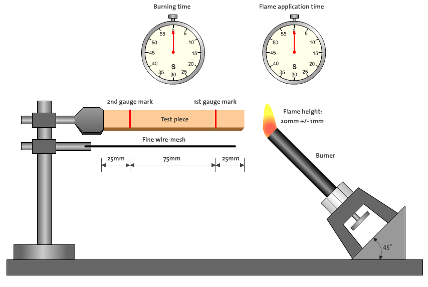
94 – HB Testing [2]
Strip dimensions – Length 125 mm (5 in) x Width 13 mm (0.5 in) x Thickness [typically 0.7 mm (1/32 in) or 1.5 mm (1/16 in) or 3.0 mm (1/8 in)].
This test is conducted using a horizontal strip with the following requirements:
| Flame application | 20 mm high Tirrill burner flame |
| Flame application time | 30 s |
| If the flame front reaches the first mark within 30 s, flame applications discontinued. | |
| Test criteria | Burning rate in V | Flammability rating |
| Test specimen thickness 3-13 mm | ≤40 mm/min | HB or HB40 |
| Test specimen thickness ‹ 3 mm | ≤75 mm/min | HB or HB75 |
| Flame is extinguished before first mark | =0 mm/min | HB |
See interesting animation at:
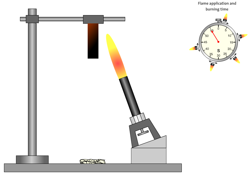
UL 94 V Testing [2]
These tests are conducted with the strips mounted vertically and need to meet the following requirements and have cotton with cotton wadding under the test strip which may or not ignite depending on the test:
| Flame application | 20 mm high Tirrill burner flame |
| Flame application time | 2 x 10 s |
| The second flame application time begins as soon as the ignited specimen is extinguished or immediately if the specimen does not ignite. | |
| Flammability rating UL 94 | V-0 | V-1 | V-2 |
| Burning time after flame application (s) | ≤10 | ≤30 | ≤30 |
| Total burning time (s) (10 flame applications) | ≤50 | ≤250 | ≤250 |
| Burning and afterglow times of specimens after second flame application (s) | ≤30 | ≤60 | ≤60 |
| Dripping of burning specimens (ignition of cotton batting) | no | no | yes |
| Specimens completely burned | no | no | no |
See interesting animation at:
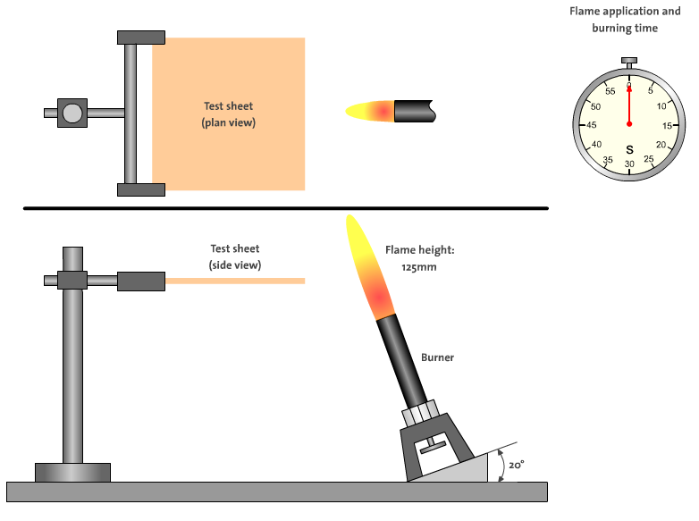
Flammability UL 94-5 V [2]
UL94 5VA & 5VB FLAMMABILITY STANDARD
Specimens
- Bars: Length 125 mm (5 in) x Width 13 mm (0.5 in) x Thickness [typically 3.0 mm (1/8 in)].
- Plaques: Length 150 mm (6 in) x 150 mm (6 in) x Thickness [typically 3.0 mm (1/8 in)].
For bar specimens, the specimens are mounted with the long axis vertical.
Procedure for Plaques
Same as for bars except that the plaques are to be mounted on the horizontal plane with the flame applied to the center of the bottom surface of the plaque.
Requirements for 5VA
- The specimens may not burn with flaming or glowing combustion for more than 60 seconds after the fifth application of the test flame.
- The specimens may not drip flaming particles that ignite the dry absorbent surgical cotton located 300 mm below the test specimen.
- Plaque specimens may not exhibit burn through.
Requirements for 5VB
- The specimens may not burn with flaming or glowing combustion for more than 60 seconds after the fifth application of the test flame.
- The specimens may not drip flaming particles that ignite the dry absorbent surgical cotton located 300 mm below the test specimen.
- Plaque specimens can exhibit burn through.
This is the most rigorous test and conducted on a sheet or actual specimen cut from the enclosure and evaluates both the burning and afterglow times and any holes that are formed as well as dripping of the burning test specimen.
| Flammability rating UL 94 | ||
| Test criteria (test specimens) | 5 VA | 5 VB |
| Burning and afterglow times of specimens after fifth flame application | ≤60 s | ≤60 s |
| Dripping of burning specimens | no | no |
| Test criteria (sheets) | ||
| Hole formation | no | yes |
See interesting animation at:
Thin Materials and Foams:
Materials that are thin gauge – typically > or = 10 mil, or very flexible may distort, shrink or flex during the 94V test. These materials can be tested using the special 94VTM method and classified as 94VTM -94VTM-0 = 94V-0, 94VTM-1 = 94V-1, etc.
There are also classifications that apply to low density foam materials – HF-1, HF-2, HBF.
UL 60950-1
Now let us look at the implications for the plastic designer using UL60950-1 as an example. There are four needs that the he/she needs to meet in order to qualify the product for this certification. These are:
- Minimum wall thickness to meet the flammability requirements
- Minimum strength to meet the impact and drop requirements
- Minimum and strategic openings to prevent access to electrical or mechanical hazards, and
- Nonflammable materials under certain electrical components such as coils to prevent flaming drippings from falling to the supporting surfaces
The requirements vary based on its weight, if it is mounted to a wall, hand held or portable.
The enclosure types are:
- Fire Enclosure: part of the equipment intended to minimize the spread of fire or flames from within.
- Mechanical Enclosure: part of the equipment intended to reduce the risk of injury due to mechanical and other physical hazards.
- Electrical Enclosure: part of the equipment intended to limit access to parts that may be at hazardous voltages or hazardous energy levels.
- Decorative Part: part of the equipment, outside the enclosure, which has no safety function.
Mechanical Strength
General
- Adequate mechanical strength or construction that no hazard is created when subjected to normal handling.
- Damage to finish, cracks, dents and chips are disregarded if they do not affect safety.
Steady Force
External enclosures are subjected to a steady force of 250 N ± 10 N for a period of 5 seconds, applied in turn to the top, bottom and sides of the enclosure fitted to the equipment, by means of a suitable test tool providing contact over a circular plane surface 30 mm in diameter. However, this test is not applied to the bottom of an enclosure of equipment having a mass of more than 18 kg.
Impact
A solid smooth steel ball, approximately 50 mm in diameter and with a mass of 500 g ± 25 g, is permitted to fall freely from rest through a vertical distance of 1.3 m onto the sample. Vertical surfaces are exempt from this test.
In addition, the steel ball is suspended by a cord and swung as a pendulum in order to apply a horizontal impact, dropping through a vertical distance of 1.3 m onto the sample. Horizontal surfaces are exempt from this test.
Stress Relief Test
Shrinkage or distortion of the material due to release of internal stresses caused by the molding or forming operation does not result in the exposure of hazardous parts.
Openings in Enclosures
Top and side openings – should not allow external objects to fall onto components causing a hazard.
The tip of the UL articulated finger (see figure 2), shall not contact parts causing an electrical or mechanical hazard.
| Material Flammability RequirementsFire Enclosures: |
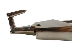 Figure 2 UL Articulated Finger [4]
Concluding Thoughts:
To conclude, the designer has to meet the following three UL specific requirements in terms of the plastic parts:
- Select materials that meet the flammability requirements in terms of the UL ratings
- Meet the impact and drop requirements
- Make sure the minimum thickness is maintained to meet the above
Material Selection
So how does one find the right material with the right flammability?
All plastic materials that have been tested carry a UL “Yellow Card” as illustrated in Figure 3. This card lists the flammability rating of a material at various thicknesses. Material suppliers will also supply similar data.
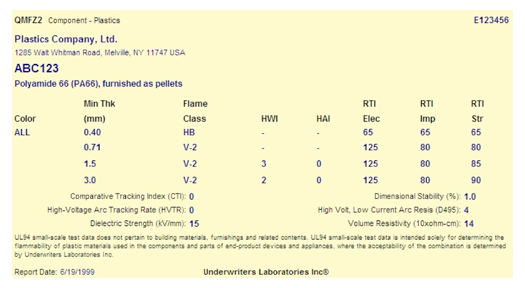
Figure 3 UL Yellow Card
One of the best ways to search for the flammability (and most other engineering and processing properties) is to use the UL Prospector at:
Plastic Flammability
Thus a search for Lexan 500 will result in the following:
Strength and Warpage
Plastic part strength and warpage can be significantly (adversely) affected by errors in the design of nominal wall, ribs thickness, sharp internal corners, etc. in the hyperlinked discussion on the subject. .
Here I would like to introduce Geometric DFX which can quickly check for these design errors.
Geometric’s DFX solution can also help engineers verify their designs for various downstream guidelines, best practices and standards. These could be related to manufacturing, assembly, performance, quality, etc. It also provides an extensible and customizable framework which allows organizations to build in their own best practices and capture organizational knowledge for early reuse at the design stage.
Thus from the UL point of view any design errors that would cause warpage (to expose hazardous areas) or reduction of impact strength can be quickly detected and corrected.
Figure 4 Geometric DFX solution
Maintain Minimum Wall Thickness
Geometric also provide a specialized thickness measurement tool, GeomCaliper, which vastly simplifies the thickness analysis activity for a CAD model. This achieves two objectives:
- Make sure no area of the plastic walls is under the required thickness to meet the UL requirements
- Help ease and expedite the UL certification with the graphical plot of the thickness that the UL examiner can verify
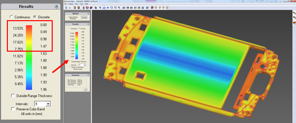
Figure 5 GeomCaliper : Wall thickness plot
Going back to the example of Lexan 500 above, if the the UL requirement was UL 94 V0, the minimum thickness required would be .060 inch or 1.5 mm and all the areas with thickness less than 1.5 mm in the plot (as shown within the red rectangle) would be unacceptable.
References
[1] Adapted from Safety Certification
[3] Adapted from International Standard IEC 60950-1
[4] Source: [Image]
![[Image]](http://www.iectestingequipment.com/photo/ps2471575-ul_standard_articulated_test_finger_probe_ul474_fig_5_1_ul507.jpg)
[5] Source: www.dfmpro.com