This is a continuation of the discussion from Part 1, 2 and 3.
Let us start with a quick summary:
Unlike metals, plastics are not capable of withstanding long-term stresses. A significant number of failures occur due to long term stresses. These long-term stresses can result from:
- Willful disregard of this inherent characteristics of the materials
- Lack of knowledge of the characteristics
- As a result of poor choice of
- Materials
- Design (non-observance of design rules)
- Tooling errors
- Poor processing
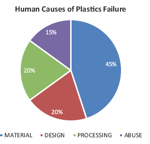
In his book, Failure of Plastics and Rubber [1], David Wright conducted an analysis on 5,000 failed parts and came up with the causes for the failures shown in Figure 1.

Figure 1 – Causes of plastics failure [1]
In my opinion, however, failures due to design deficiencies may be the cause of most of them and sometimes mistakenly attributed to the other three causes.
As an example, in part one we discussed the loss of chemical resistance due to inherent or applied stresses and failures due to sharp internal corners. Other examples of sharp internal corners showed reduction in both the chemical resistance and mechanical strength. These would ordinarily be labeled as material failures or the material being a significant contributor.
In part 2, failures were broadly classified into types of failures, namely:
- Catastrophic failures
- Major failures leading to injury, recalls and serious revenue loss
- Failures leading to loss of revenue, reputation and customer base
- Failures giving plastics a bad name
Plastic parts were also shown to perform four types of functions.
Some real-life examples were then discussed for failures that give plastics a bad name in general.
Part 3 provided some real-life examples of:
- Catastrophic failures
- Major failures leading to injury, recalls and serious revenue loss
- Failures leading to loss of revenue, reputation and customer base
In the concluding part, let use discuss some very specific requirements for the product being designed where, just maybe, the design rules may be violated without sacrificing the critical visual or critical needs.
Table 1 lists the effects for amorphous materials. The first two columns list the most common defect types based on whether the parts are painted or not. The following seven columns list the critical visual and functional requirements. The colors in the rows indicate severe effect (red), moderate effect (yellow) and no effect (white) if the design violations do occur. Green rows indicate the possible enhancement of these requirements if the parts are painted.
The number within the cells explain the phenomenon that causes the effect. For example, sharp corners (1) create stress concentration resulting in failures in the area and consequently reduce the tensile or impact strength. Paint (15) may have better chemical resistance than bare plastic, enhancing the chemical resistance of the part.
Amorphous Materials, Table 1:

1 Create stress concentration resulting in failures in the area
2 A Reduced impact strength at low temperatures
3 Create local thin areas if the outside corner is radiused causing possible cosmetic defects or warpage
4 Create local high stress areas causing loss of chemical resistance
5 Create higher molded in stresses due to uneven shrinking and packing
6 A Will cause sink marks and/or shadows at the intersection
7 Create uneven shrinkage and warpage in different areas of the part
8 Create higher molded in stresses causing uneven and uncontrolled warpage in thermal cycling
9 Inadequate tangling of opposing polymer chains or trapped gases and at knit line
10 Create unsightly areas with variation in appearance
11 Knit line may be located in a high impact area
12 Warped parts may be “unwarped” during assembly causing long term stresses
13 Scuff marks
14 Warpage due to possible uneven ejection
15 Solvent in paint may attach plastic
16 Paint may hide cosmetic defects
17 Paint (such as epoxy) may have better chemical resistance than plastic
18 Solvent in paint may cause distortion
19 Solvent in paint may cause distortion
Table 2 similarly lists the effects for semi crystalline materials. For the most part, the defects and their consequences are fairly similar. There are some subtle differences in the chemical resistance, though. Since these materials are inherently much more chemical resistant than the amorphous materials, for these parts the only enhancement the paint provides is hiding the superficial molding defects such as flow marks and very shallow sink marks.
Semi-Crystalline Materials
1 Create stress concentration resulting in failures in the area
2 Reduced impact strength at low temperatures
3 Create local thin areas if the outside corner is radiused causing possible cosmetic defects or warpage
4 Create local high stress areas causing loss of chemical resistance
5 Create higher molded-in stresses due to uneven shrinking and packing
6 Create uneven shrinkage and warpage in different areas of the part
7 Will cause sink marks and/or shadows at the intersection
8 Create higher molded in stresses causing uneven and uncontrolled warpage in thermal cycling
9 Inadequate tangling of opposing polymer chains or trapped gases and at knit line
10 Create unsightly areas with variation in appearance
11 Knit line may be located in a high impact area
12 Warped parts may be “unwarped” during assembly causing long term stresses
13 Scuff marks
14 Warpage due to possible uneven ejection
15 Solvent in paint may attach plastic
16 Paint may hide cosmetic defects
17 Paint (such as epoxy) may have better chemical resistance than plastic
18 Solvent in paint may cause distortion
Elastomeric Materials, Table 3:

Table 3 lists the effects for elastomeric materials used by themselves or for over-molding over other plastics or metals. Since these parts do not see very high stresses due to their very low modulus, the requirements are much more relaxed.
NA Not applicable
1 May result in flow marks.
2 May result in poor adhesion between substrate and overmold in over molded parts and subject to peeling.
3 May result in sink marks and /or shadows.
4 May result in scuff marks.
NA* Elastomers are seldom painted.
Table 4 suggests some guidelines on how the design rules can be relaxed based on less stringent requirements. Red indicates the values if the requirements are critical, yellow if not so.
Relaxed Requirements, Table 4:

[1] Greater lengths can be successfully molded with balanced filling from both sides of the rib achieved through flow simulation.
[2] Low draft angles may be adequate if the steel is polished in the direction of draw, the steel has added lubrication such as teflon impregnation or if the material has a lubricant such as teflon added.
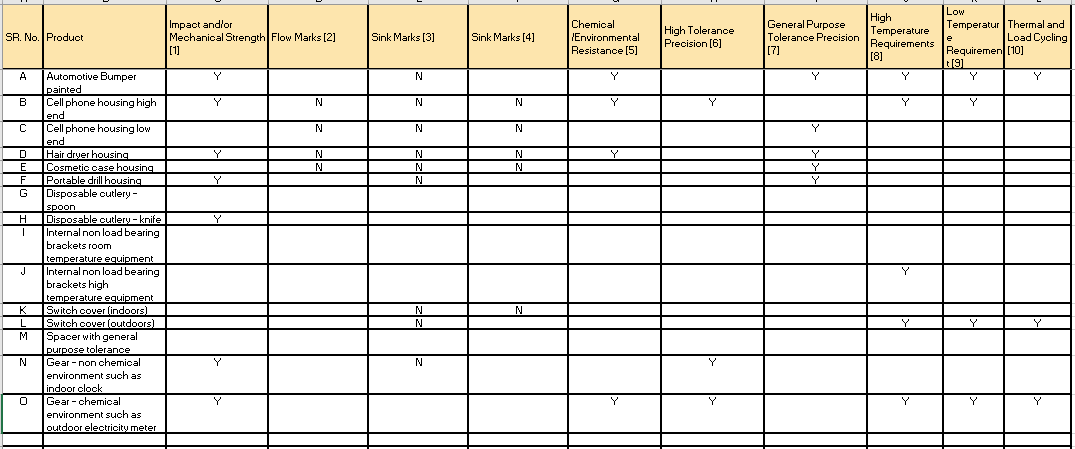
Table 5 specifies the characteristics that may be important for the products used in the examples. Based on these specific functional requirements certain rules may be relaxed in these products per table 4.
As an example, a relatively heavy high-end cell phone may need more mechanical strength than a much lighter low end one. (Remember, Force=Mass x Acceleration? Thus, a low-end phone sees much lower force on drop than a high end one). Also, a consumer may not be bothered as much by a cracked low-end phone as compared to a high-end phone.
Notice the difference in mechanical strength requirements even between a disposable knife and spoon. Try cutting a steak with a poorly designed (and therefore mechanically weak) plastic knife. The spoon on the other hand, does not have this mechanical requirement.
Some Common Examples, Table 5:

[1] Product will be subject to moderate to high impact and mechanical stresses
[2] Product will not be painted and should be free from flow marks
[3] Sink marks which will have measurable depth that will not be hidden by paint
[4] Sink marks which do not have measurable depth and can be covered by paint
[5] Products needing to withstand environmental solvents including high humidity, sweat, cosmetics and body lotions
[6] Products needing precision tolerance for closely mating static or moving parts
[7] Products needing general tolerance such as clearance holes or having no mating parts
[8] Products subject to extreme outside day or other hot ambient temperatures
[9] Products subject to extreme outside night or other cold ambient temperatures
[10] Products subject to outside extremely hot and cold temperature cycling
Examples
A Automotive Bumper painted
B Cell Phone Housing High End
C Cell Phone Housing High End
D Hair dryer housing
E Cosmetic cases
F Portable drill housing
G Disposable cutlery – spoon
H Disposable cutlery – knife
I Internal non-load bearing brackets room temperature equipment
J Internal non-load bearing brackets high temperature equipment
K Switch cover (indoors)
L Switch cover (outdoors)
M Spacer with general purpose tolerance
N Gear – non-chemical environment such as indoor clock
O Gear – chemical environment such as outdoor electricity meter
DFMPro and Simulation Tools Come to the Rescue!
DFMPro optimizes the overall inherent design to prevent short and long term visual, functional, processing or tooling issues by going through the design and highlighting all the design issues.
The parameters can be customized for the part based on the functional requirements as explained above.
Structural and Flow simulation takes the error free design provided by the use of DFMPro and optimizes it for performance through proper dimensional veracity, elimination of manufacturing issues such as elongated holes, cracks, porosity and optimizes it for flow, cooling, heating, venting, ejection, gate(s), and location and strength of knit line, etc.

Together, they provide a powerful – a one, two punch!
To conclude:
In the new competitive world, product designers are under tremendous pressure to produce robust designs at a minimum cost and in the fastest possible time.
A ready solution such as DFMPro can be of tremendous value
- By helping the design engineer avoid manufacturing and performance issues right at the design stage.
- Both new and seasoned engineers can look at it as a sidekick checking for design errors along with the explanations at the click of a button.
- By being the designer’s dependable partner in guarding against the errors with total objectivity and thoroughness that conventional design check processes with their inherent subjectivity will likely miss.
- By being a powerful ally to reduce costly mistakes occurring either due to human error or lack of manufacturing and performance related knowledge.
DFMPro can be analogous to using a spell checker in a Word document which quickly detects the errors and recommends alternative solutions.
[1] Modified from D. Wright; Failure of Plastics and Rubber Products, Smithers Rapra (2001) p. 6
Never Miss an Update
Subscribe to the HCL DFMPro Blog weekly digest
and stay informed about the latest content from industry leaders.