Practical Adherence to Design Rules – a Matter of Choice?
So, you have designed successful parts with sharp inside corners, uneven walls, thick ribs, low draft angles, etc. Based on this, you feel strict compliance to these rules may be an overkill. You further feel that taking care of these design requirements adds unnecessary time to the completion of the design. These requirements may also add to the overall cost. The above statements may or may not be true. Let us start with the basics.
Long Term Stress

Fig [1]
Unlike metals, plastics are not suitable for long-term tensile stresses. These stresses can be the result of a continuous load, warpage, or any other design, material, processing, or tooling-related issues. Therefore, any design, tooling, or processing issues that induce avoidable long-term stresses should be avoided. Continuous stress can ultimately cause the part to fail in the short or long term. Let us look at some of the details. The following deficiencies can be imparted into plastic parts, sometimes substantially. More explanation of these items will follow.
Impact Strength
- Inside corner radius
- Stress concentration
- Thin to thick flow
- Molded in stresses due to non-uniform packing
- Knit line position and strength
- Gate location
- Wall thickness uniformity
- Molded in stresses
- Long thin ribs
- Molded in stresses due to non-uniform packing
Cosmetics
- Rib thickness
- Sink marks
- Draft
- Scuff marks
- Warpage
- Wall thickness non-uniformity
- Nonuniformity of “sheen”
- Warpage
- Knit line appearance
- Thin to thick flow
Additionally, avoidable stresses and violation of other design rules can also lead to deficiencies in:
Chemical Resistance
- Rib thickness
- Lack of compressive layer around the sink mark
- Draft
- Warpage causing loss of compressive layer
- Wall thickness non-uniformity
- Molded in stresses
- Knit line strength
- Thin to thick flow
- Inside corner radius
- Stress concentration
Tolerance Precision
- Rib thickness
- Warpage
- Draft
- Warpage
- Wall thickness non-uniformity
- Warpage
- Unpredictable shrinkage
- Inside corner radius
- Stress concentration
High Temperature Requirements
- Rib thickness
- Molded in stresses
- Draft
- Warpage – molded in stresses
- Wall thickness non-uniformity
- Molded in stresses
- Inside corner radius
- Stress concentration
Thermal and Load Cycling
- Rib thickness
- Warpage
- Draft
- Warpage
- Wall thickness non-uniformity
- Warpage
- Unpredictable shrinkage
- Inside corner radius
- Stress concentration
Cost
All of the above result in higher cost
- Extra tooling costs
- Scrap cost
- Sorting cost
- Selective assembly cost
- Repair and warranty costs
- Opportunity costs
- Additional resource costs
Back to the Basics
Unlike metals, plastics are very poor conductors of heat.Figure 1 below shows what happens to the part in the process of being molded. The left figure shows the part as it comes out of the mold. The outside layers come in contact with the relatively cold mold surfaces and the air. The inside layers are insulated by the outside layers. As a result, they remain hot much longer than the outside layers and continue to shrink while the outside layers are “frozen”. See the middle figure.
The net result is that the outside layers are pulled in by the inside ones and are in a continuous state of compressive stress. The exact opposite happens to the inside layers and they are locked in state of tensile stress. See the right figure.
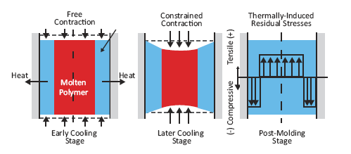
Figure 1[2]
Figure 2 shows a Polycarbonate dog bone that the compressive layer has been carefully machined off on the top. Notice how now the tensile layer under it is pulling in the top layer resulting in the concave shape.
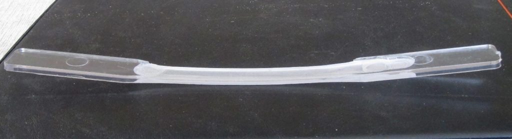
Figure 2
Since most parts fail under maximum tensile stresses on the outer fiber, the compressive layer adds to the strength of the part.
Compressive layers on the two side sides prevent the ingress of solvents in to the inner layers and prevent the degradation of the long molecular chains that make up the plastic.
Figure 3 and 4 are simulation of stresses on a dog bone being bent. See Figure 3 and 4. In the unbent state, there is the friendly compressive layer on the top indicated by the blue color. Upon bending, however, the outer stresses turns to tensile indicated by the red color.
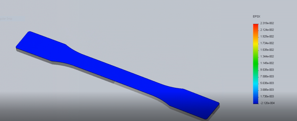
Figure 3
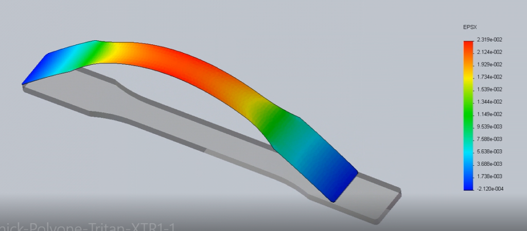
Figure 4 [3]
In my training sessions I take two polycarbonate dog bones (polycarbonate is extremely solvent sensitive). The first piece I literally dunk in acetone and leave aside. The second one I bend back and forth until my elbows start to ache. Nothing happens to the dog bone. I then bend it slightly and apply a tiny drop of acetone. The part catastrophically breaks in to two.
I then go back to the first dog bone where the acetone has completely evaporated. I take this dried piece and bend it back and forth until my arms ache again. NO failure.
What just happened? The compressive layer on the first part prevented the ingress of the acetone into the inner layers. No failure. The tensile layer on second one allowed the ingress. Catastrophic failure!
What happens to a part that is warped when it comes out of the mold and you “unwarp” it in the process of assembling it to its mating part? You introduce a tensile layer on the warped part in the process. What happens to its strength? What happens to its chemical resistance?
Lack of Uniform Wall
Now let us look at figure 5. The left side of the part is 50% thinner than the right. The right-hand photograph is the infrared thermal profile of the part. The left side having a much less heat content has cooled down to 118 deg C while the right side with its heavier section is at 238. As the part continues to cool to room temperature, the left side is done shrinking while the right continues to shrink for a long time. This introduces a very high stress at the junction which weakens the part both mechanically and chemically. It also causes the part to warp.
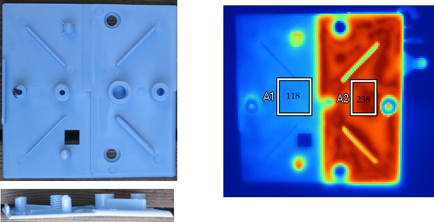
Figure 5 [4]
Figure 6 shows a hand-held device with severe cracks caused by merely the mild lotion and sweat on the user’s hands. This was the result of a sudden change of wall thickness on the side wall accompanied with a sharp corner. And that brings us to the final topic of discussion in part 1 of the blog – sharp internal corners.
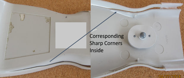
Figure 6
Sharp Internal Corners
Figure 7 shows the rise in stress concentration as the R/WT ratio decreases (see figure for explanation of the terms).
In a well-designed part, imparted stress should be uniformly distributed over as large an area as possible. The opposite of this are stress concentrators which concentrate the stress on a very small area causing it to fall.
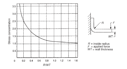
Figure 7 [5]
Figure 8 shows the catastrophic failure a of a highly tough polycarbonate part in a small drop to carpet because of the sharp corners.
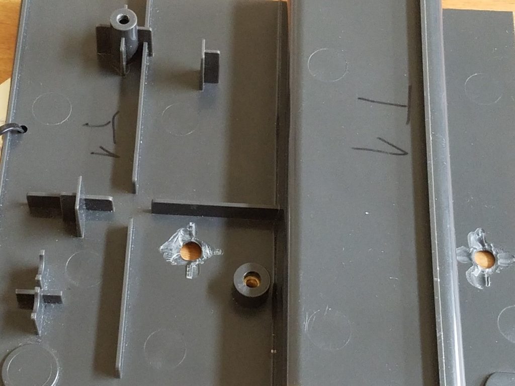
Figure 8
In the next part of the blog I will go through some actual examples of errors ranging from ones that can cause death to merely a nuisance value on a disposable plastic item.
References
[1] Source: Anonymous
[2] Adapted from http://www.dc.engr.scu.edu/
[3] Courtesy of Joseph P McFadden, Sr.
[4] Photograph Courtesy of John Bozzeli
[5] Source: Jordan Rotheiser; Joining of Plastics, Handbook for Designers and Engineers, Hanser Publishers, Munich (2009)
Never Miss an Update
Subscribe to the HCL DFMPro Blog weekly digest
and stay informed about the latest content from industry leaders.