5 Design Rules for: Problem Free Injection Molded Plastic Parts
In the last couple of decades, use of lightweight alternatives such as plastics and composites has dramatically increased, with its applications well entrenched in automotive, aerospace, consumer electronics industry.
Today’s car for example, has more than 150 kilograms of plastics on board in the form of seats, dashboards, bumpers, and engine components. Boeing 787 on the other hand has 50% carbon fibre-reinforced plastic and other composites in its airframe. The company says it has used more carbon composites and plastics than ever before in the 787 model.
Plastics offer good mechanical properties and are relatively lighter than metal, making products more efficient, while providing enough toughness to withstand the test of time. However, it is important that designers be sensitive to certain physical and mechanical properties of plastics as it is not as strong as metal, has relatively lower density than metal and is poor conductor of heat and electricity
Injection molding is the most commonly used manufacturing process but due to its intricacies product designers need to make adequate design considerations to ensure that part designs focus on maximizing molding performance and reducing tooling costs , an area that often plague the injection molding industry.
Plastics tend to have higher rates of thermal expansion than metals and thicker sections shrink more than a thinner section, resulting in warpage or sink mark during the molding process. Stress concentration is another area that is of particular concern for plastic part manufacturing. These stresses can be the result of a continuous load, warpage, or any other issue related to design, material, processing, or tooling factors. Additionally there can be many latent defects in plastic parts that can not be detected with routine quality control.
Plastic part performance and cost can be significantly enhanced by proper part design features. Through the use of simple designs and by following general moldability guidelines for plastic parts, design engineers can avoid problems occurring during manufacturing and also reduce the cost of parts. These factors require designers to introduce adequate design features that can lessen the stress level within a part and help develop low-shrinkage, warp-free parts.
Consider the following injection molding design considerations for designing better plastic parts
1. Radius
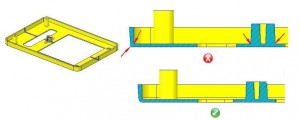
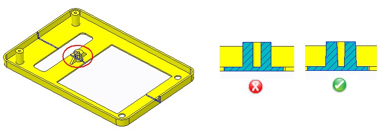
A design with corners always needs to accommodate large radii. Sharp corners spell stress thereby affecting the manufacturability of parts. Corners such as the attachment between bosses and surfaces which are often overlooked require scrutiny.
 The radius should always be with regards to the part thickness thereby eliminating the prospects of high-stress concentration and resulting in the breakage of the plastic part. General guideline suggest that the thickness at the corner should be in the range of 0.9 times the nominal thickness to 1.2 times the nominal thickness of the part.
2. Wall Thickness
Given the different nature of the composition of plastics, plastic parts should always have walls with uniform thickness. Swerving away from the recommended would give rise to unfavorable results such as shrinkage and warpage. Apart from this, uniform wall thickness gives the assurance of minimum manufacturing cost. This further ensures quick cooling which in turn lets one produce more parts in a short span of time and optimum utilization of resources which is much sought after. And lighter parts have never been considered inconvenient.

General guidelines suggest that wall thicknesses for reinforced plastic materials should be between the range of 0.75 mm to 3 mm and those for unfilled materials should be 0.5 mm to 5 mm.
3. Determine an apt location for gate
While it is recommended to have a plastic design with a uniform wall thickness, we understand the need to have variations in few designs. In such unavoidable situations, having a proper gate location would decide the success of the part. Experts recommend designs with the gate at a location at which the melt enter the thickest section of the cavity only to flow out of a narrower region.
4. Draft
Plastic heavily relies on mold draft in the course of its removal from the mold. Due to which plastic parts are to be designed with a taper (or, draft) in the direction in which the mold moves. In such case, the lack of an appropriate draft would make the removal of plastic parts almost impossible.

A design with sufficient draft is always considered to be a good practice. 1.5 degrees for a depth of 0.25mm is usually recommended by design experts. General guidelines suggests that a draft angle of 0.5 degrees is recommended for core and 1.0 degrees for cavity
5. Ribs
 A known aspect of plastic is its stiff nature. Given this, the inclusion of ribs in a design is often recommended which adds to the bending stiffness. Ribs are pocket-friendly and a convenient option, the end result of which is often well received by both the designer and the manufacturer.
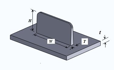
But a plastic designer should always take the wall thickness into consideration at the time of including a rib in a plastic design. Thick and deep ribs can cause sink marks and filling problems respectively. Rib thickness of a part should never exceed the wall thickness.
General guidelines suggests that rib thickness at its base should be around 0.6 times nominal wall thickness of the part. Failing to include a proper rib would eventually lead to the distortion of the plastic part.
Learn more about what makes a great plastic part design. Download the complete DFM eBook
