DFMPro for Casting Design
Several of the tooling and casting requirements of a part can be addressed at the casting design stage. If the requirements are not addressed at design stage, it will result in iterative designs and rework when it reaches the die caster, resulting in longer manufacturing time and overall time to market. DFMPro is a CAD integrated Design for Manufacturability Software (DFM) solution which allows the designer to check his designs for producibility. DFMPro for casting design assists design engineers in identifying features of a design which are difficult, expensive and impossible to manufacture, at the design stage itself.
DFMPro Casting Design Guidelines
Casting is one of oldest manufacturing processes and it is still preferred by various industries with its demand primarily driven by the automotive industry. Though there are many kinds of casting processes with distinct design and manufacturing guidelines, we will look at the ones which are common to most casting processes.
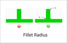
Fillet Radius
Sharp corners, edges and rapid changes in cross-section should be avoided in cast parts. Fillets should be added to sharp corners and edges. Inside corners should be designed with fillets and outside corners should have radii as large as possible. Depending on the casting process, minimum fillet radii should be provided on inside and outside corners of the components. For example, in die casting, a minimum radius of 1.5 times the wall thickness should be provided.
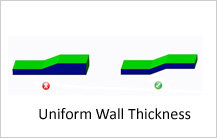
Uniform Wall Thickness
Wall thickness should be kept uniform as it helps to create high quality cast parts. Sudden variations and geometry changes and in wall thickness affects metal flow, resulting in air enclosures and poor surface finish of parts. The recommended range of wall thickness is two times the thinnest wall section. The transition from thick to thin walls should also be as gradual as possible.
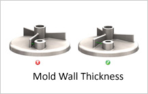
Mold Wall Thickness
Mold wall thickness is an important aspect to be considered in casting. If the mold wall is too thin and elongated, stresses are developed in the mold, reducing mold life. Also, special materials are required to create the molds and they may need regular replacement and service. Ribs and bosses which are too close to each other can result in thin mold walls. Hence the minimum allowable mold wall thickness should be decided based on process and material considerations. The minimum clearance between features of a cast component will be based on the casting process, component material and tool material.
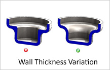
Wall Thickness Variation
Wall thickness variations in the casting result in differing rates of cooling, shrinkage, warping and distortion. Ideally, the wall thickness should be uniform throughout the part (equal to the nominal wall thickness). In reality, this variation is unavoidable due to functional and aesthetic requirements. However, the amount of variation should be minimized and within a certain tolerance limit.
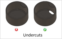
Undercuts
It is recommended that undercuts should be avoided for ease of manufacturing. Undercuts require additional mechanisms, adding to mold cost and complexity. Clever part design or minor design concessions can often eliminate complex mechanisms for undercuts.
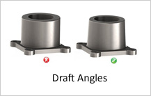
Draft Angles
Draft is the taper given to core and cavity for easy removal of casting (or pattern). Adding proper drafts on the cast parts improves cycle time and quality of surfaces. The sidewalls of the castings and other features perpendicular to the parting line must be drafted as much as possible. The draft angle will depend upon the type of material and varies inversely with height of the wall.