
Plastic provides versatility and strength across a wide range of applications. In the last few blogs, we have covered plastic part design guidelines. In this article, we will cover thermoforming part design guidelines. We all are aware; the thermoforming is most suitable for shallow-shaped parts where the heated plastic sheet is formed over male or female mold to achieve thin uniform wall thickness. Broad level process is classified into two categories.
- Vacuum Thermoforming
- Pressure Thermoforming
Thermoforming parts are mostly used in our consumer-products like packaging, nonpackaging items, containers for foods, trays, foam, egg cartons, disposable cups, small tubs, dairy products, etc. Other applications are automobile interiors, aircraft interior panels, sports car body, lighting panels, and fixtures.
What is Thermoforming?
It is a single-sided plastic fabrication process where a heated plastic sheet is formed with either male or female mold into a three-dimensional shape. Post trimming & finishing is done to get the final part.
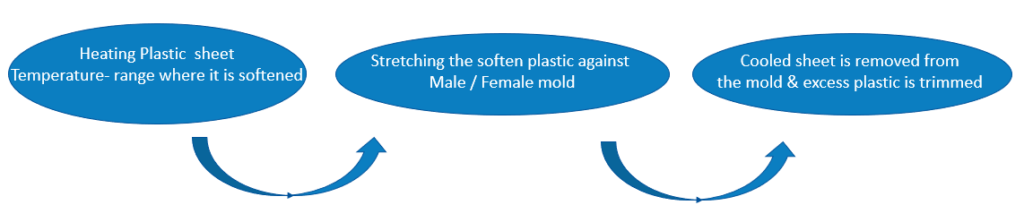
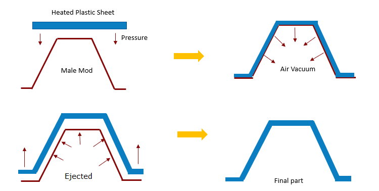
Vacuum Thermoforming:
Plastic sheet is heated to a forming temperature & stretched onto a single-surface mold and forced against the mold by a vacuum. It is relatively cheaper process as compared to other thermoforming processes. Figure 1 shows the process steps.
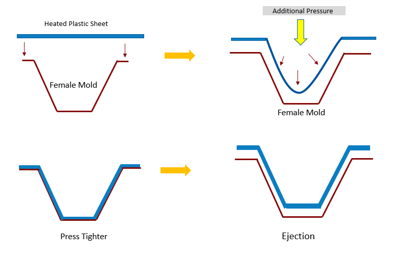
Pressure Thermoforming:
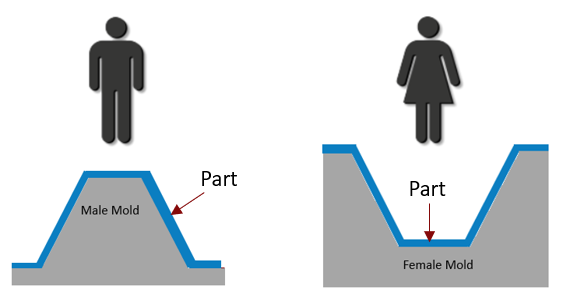
In pressure forming additional compressed air is used to push the plastic sheet against the mold. Figure 2 shows the process steps & Figure 3 shows male and female mold.
Advantages: Pressure Thermoforming V/S Vacuum Thermoforming
| Pressure Thermoforming | Vacuum Thermoforming |
| Mold Cycle is fast | Mold cycle is Slow |
| Plastic sheet can be formed with lower heat as additional forcing pressure is available | High Plastic sheet temperature |
| Good Surface Finish | Lower surface finish |
| Create more complex shapes | Create less Complex shapes |
| High Dimensional Control | Low Dimensional control |
| Efficient for large parts | Efficient for small parts |
Plastic sheet can be formed with lower heat as additional forcing pressure is available
Thermoforming Materials:
All thermoplastic materials that are available in sheet or roll form can be thermoformed. Following are few materials & its characteristics. Few simple yet integral tips which need to be taken into consideration while designing thermoforming parts.
| Material | Characteristics |
| High Impact Polystyrene (HIPS) | Easy to process, extremally well and low-cost material |
| Acrylonitrile Butadiene Styrene (ABS) | Available in virtually any color with a variety of textures, less brittle than HIPS |
| High Density Polyethylene (HDPE) | Very tough, durable material not rigid as like ABS Suitable for applications that require high toughness like material handling trays. |
| Polypropylene | Slightly more rigid and withstands higher temperatures than HDPE |
| Poly Vinyl Chloride (PVC) | It is typically grey or white in color, used in chemical tanks & plumbing fixtures. |
| Polycarbonate | It is not as rigid as Acrylic but has much better impact resistance. It has extremely high toughness and impact resistance. It can also withstand higher temperatures than most thermoplastics, up to 210 degrees F. |
Few simple yet integral tips which need to be taken into consideration while designing thermoforming parts.
Minimum Draft Angle:
The appropriate draft angle should provide to minimize the de-molding issue. Guidelines suggest female features should have draft angle 1.5 to 2.5 degrees & for male features it varies from 4 to 6 degrees. Sometimes it needs higher values for deep textures.
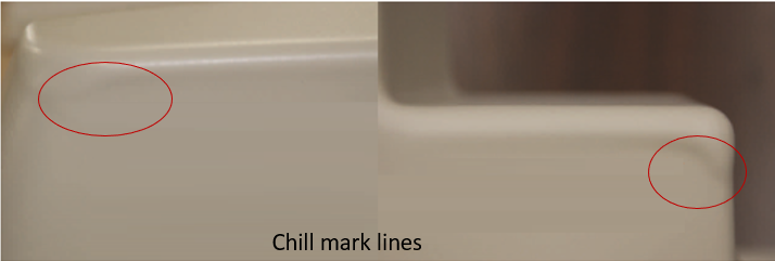
In case of female mold, the draft angle is less as compared to male mold, as the material shrinks away from the mold. However, in case of male mold, the draft angle is more as the material shrinks tighter towards the mold wall. Due to small draft angle, when sheet stretches over the mold, the first contact point cools faster & which reduces material flow characteristics & material gets distributed unevenly and creates ‘chill mark lines’ as depicted in Figure 4
Draw Ratio:
The draw ratio is one of the major design considerations which used for defining starting sheet thickness.
By using draw ratio calculations, one can easily find out starting sheet thickness.
A general guideline suggests a maximum draw ratio would be a 3:1 ratio.
Example 1: Assume a part is 10″x 12″x 2″ deep.
Draw Ratio will be:
Surface Area = 2(10″ x 2″) + 2(12″x2″) + 10″ x 12″ è 40″ + 48″ + 120″ = 208″
Footprint Area = 10″ x 12″ = 120″
Draw Ratio = Surface Area of the Part / Footprint of the part
è Draw Ratio = 208″/120″ = 1.7
If final wall thickness of the part is 0.10” then
Starting Sheet Thickness = 1.7 X 0.01” = 0.170” <assuming perfect material distribution>
Corner Radius:
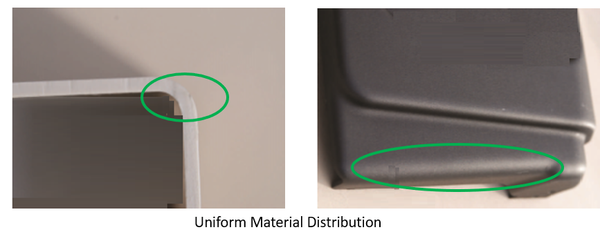
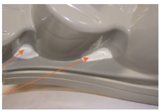
Uniform material distribution is primary design consideration in thermoforming, so proper corner radius will play are crucial role. In case of sharp corners material get overstretched & causing unacceptable thin portion or sometimes it tears with thin hole.
Such problem can be addressed by using heavy starting gauge thickness or adding adhesive additional reinforcement binder Figure 7: Reinforcement binder shows in which is applied at inside corners. The other major advantage of radii is, it distributes stress over a larger area than a sharp 90-degree corner. Figure 6: Corner Radius: Uniform Material Distribution shows correct corner radius cases.
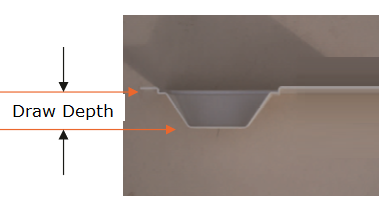
The following table shows increasing radius values based on draw depth.
| Depth of Part | Radius |
| 0” – 3” | 0.15” – 0.125” |
| 3” – 6” | 0.125”- 0.250” |
| 6”-12 | 0.250” |
DFMPro identifies such potential design errors & minimizes downstream operational issues.
Was this helpful? Want to know more about ways to address real thermoforming problems? Stay tuned for upcoming articles where we will cover other thermoforming guidelines.
References
- https://multifabmanufacturing.com/assets/Uploads/Multifab-Thermoforming-Guidelines-Rev-3-12-18.pdf
- Design for manufacturability handbook by James g Bralla