
Digital transformation of product creation process has already been finding traction with many organizations. Smarter organizations have already embarked on a journey of not just connecting but leveraging assets from multiple functions across product lifecycle.
Back in the 90’s, organizations were more focused on streamlining and centralizing financial transactions related process flows that cuts across organization. The focus was on efficiency and control at each step of transaction of the business workflow. However, that was not enough for engineering product organizations as engineering required not just paper document of financial transactions but has multiple design variables wherein the inputs may update during engineering stage as the product development is a stage-wise iterative process. Hence PLM and CAD systems have played a major role in managing the workflow and managing version and configurations of product during development process. Still the PLM environment was not covering many aspects of design because of multiple document types and disparate systems. For e.g. the 2D drawing required for manufacturing and 3D model were not in sync. The Simulation data results were stored separately. The problem was that though the ‘digitization’ of document has taken place, it was not ‘digitalized’. The hardware which was used during manufacturing was not simply capable of consuming the engineering information directly. Hence, most of the organizations used to maintain 2D Drawing for manufacturing which will have all tolerance, manufacturing information and BOM wile 3D was used for design and Geometric visualization.
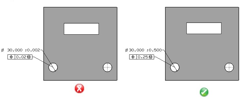
In the last decade as manufacturing hardware also started becoming smarter, it could take the engineering output as is and process it to produce the final component. For example, with modern CNC mills, a user can just upload a 3D model and G-Code is ready within minutes to begin manufacturing. The system can further assess the potential challenges in manufacturing ranging from size of the part to manufacturing features and avoid possible cases wherein it would be difficult to manufacture the component. The challenge remained that 3D models could only store part geometry information, material and few attributes. Often, engineering creates designs based on manufacturing process however, the downstream capability and impact is not known. Many times, if tolerances are too tight it needs change in manufacturing process or additional manufacturing operations need to be performed to achieve final product specifications. Hence PMI (Product and Manufacturing Information) attributes were developed for 3D model along with Geometry information. PMI is classified as part of MBD (Model based definition) practice where it incorporates all the information, which is typically provided on 2D models, thus eliminating need for having separate 2D Drawings and 3D model. Industry standards for defining PMI include ASME Y14.41-2003 Digital Product Data Definition Practices and ISO 1101:2004 Geometrical Product Specifications (GPS) — Geometrical tolerancing—Tolerances of form, orientation, location and run-out. This approach also makes it easier to convey design intent, bill of materials and configuration information for downstream consumption. The biggest advantage of this approach is that 3D becomes a single source of information and any changes to the source can be easily tracked down and impact of the same on downstream activities can be easily analyzed. Semantic and non-semantic PMI (Annotations): It is equally important that information related to PMI is correctly assigned to a specific feature. It would be impossible to process the information from just annotation. Hence PMI information needs to be carefully used to make sure that correct information is conveyed for downstream consumption of information. PMI information should be entered correctly right at the beginning of product design phase. It is sometimes difficult for design engineering to understand the impact of PMI on manufacturability which may lead to rework, extra dollars spent and longer manufacturing lead times. Additionally, this means that issues detected during manufacturing required to be traced and recommendations propagated back to design. This means such changes need to go through multiple level approval processes. Such iterations are not only expensive but also time-consuming delaying product launch schedules. A ‘Design for eXcellence’ (DFX) solution from HCL helps design engineers pinpoint such problems which impacts downstream manufacturing and use geometry data and PMI information from 3D model to recommend solution to avoid such pitfalls in design. The solution is available as ‘DFMPro’ as any easy to use add-on with popular CAD systems. Following example depicts how DFMPro highlights a problem related with hole tolerance. (Fig 1)
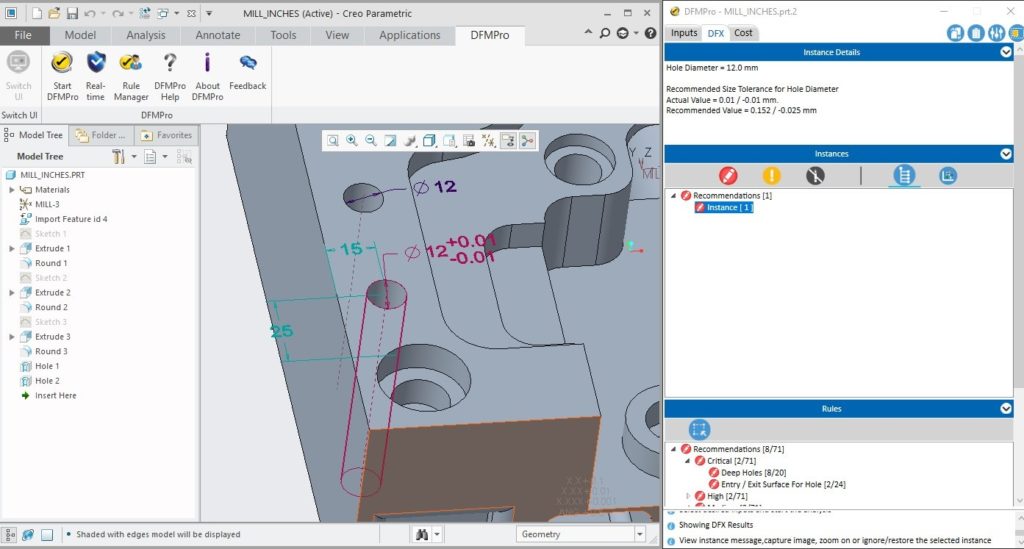
In the above example, DFMPro identifies a condition of tight tolerance and highlights to the user that the tolerance applied to the hole is too tight for manufacturing. The impact of the same is not only on ability to drill the hole but also on the cost. DFMPro enumerates impact on cost and additional manufacturing operations. Typically for such high tolerances, additional reaming operation is required. (Figures 2 )
 Figure 2. DFMPro CAD system integration – highlights feature and provides recommendation
As design engineers create designs in a step-wise process of adding feature in a sequential manner, it is important to have a quick understanding of how each feature in design is impacting manufacturability and cost. Hence DFMPro is tightly integrated inside the CAD system to make sure that immediate feedback is available for design engineers in each development phase. DFMPro leverages the geometry and PMI information from the CAD model to apply best design practices and presents user with opportunities for quality improvement and manufacturing cost reduction. Apart from upstream design and manufacturing engineering functions, downstream manufacturing functions have also started taking advantages of the PMI data. CAMWorks Tolerance based machining solution reads this PMI data and uses it automatically calculate the mean dimension and required tolerance for manufacturing and then use this information to select the correct tooling, machining strategy, and generate toolpath.

Figure 3. CAMWorks machining toolpath based on PMI data
As the dots are getting connected with this ‘Digital Thread’ and ‘3D as master’ strategy, in future it could even help not just to leverage this PMI information for ‘Processing’ but also learn from actual sensors from machines and build algorithms for design best practices. The future looks very interesting as the digital divide between design and manufacturing is narrowing, products could be built faster and easier not in days but in hours! As design engineers will have all upfront information they need at the right time, the goal of creating modular and customized products that focus not just on features but overall on customer experience will be easier to realize. References:
- Design for Manufacturability – DFMPro com
- CAMWorks com
- https://www.asme.org