
In the growing global competition, an organization is constantly under pressure to produce high- quality products at an affordable price within the limited time frame. Day by day, organizations are providing more attention to improve design & manufacturing processes. A collaborative design approach is making inroads, in which information is always up-to-date and can be accessed as a “single source” for design and manufacturing teams. The industry trend is changing, product design approach is improving, organizations are providing more focus to minimize the gap between design & manufacturing teams. Model-Based Enterprise (MBE) initiatives are gaining more & more traction, detailed PMI based 3D CAD modeling is replacing 2D drawings. However still some of the organizations use 2D drawing as “single source” and as a medium to convey design information to the manufacturing team. Let’s look few of the shortfalls of 2D manufacturing drawings:
- To read a 2D drawing accurately requires additional skill sets. Sometimes it is very difficult to visualize and understand and can be very easily misinterpreted.
- 2D drawing based approach suffers from severe lack of traceability, potential loss of information and repetition in work.
- Without looking at the 3D model, it is very difficult for the shop floor engineer to understand and interpret the dimension & tolerance.
- Creating detail drawing with dimensioning, annotations, additional notes and symbols takes additional time as compared to 3D model update.
- Considering future sustainment, maintaining and managing such drawings & documentation is difficult.
- Printing, plotting, storage of drawings & documents requires additional cost.
- Many a times, due to high workload on design & development side, only drawings get updated without updating the 3D model which returns in loss of associativity between the 3D model and drawings.
- Most importantly, in case of any design changes (rework), changes are not only required on the 3D model but also on the 2D drawings thus taking twice the effort.
To address the above challenges, large organizations have begun implementing drawing-less design and manufacturing approach. Incorporating a Model Based Enterprise (MBE) approach also helps smooth collaboration between design and manufacturing teams. Through a digital representation of CAD with manufacturing information, one can easily interpret the manufacturing operations, assembly sequence without CAD drawings & paper printouts. The information provided on the 3D CAD model like PMI, geometrical tolerance, annotation, bill of materials (BOM) can be effectively used by the manufacturing team. Following are the key benefits of MBE approach in CAD design –
- 3D models with dimensions, geometrical tolerances, annotation, surface finish symbols are easy to understand and can also be read automatically by downstream software. It improves design quality, with less ambiguity & increase design precision.
- It accelerates the engineering change order (ECOs), improves quality of CAD modeling.
- CAD model becomes single source of truth; any change in the model will automatically get updated to drawings.
- It reduces overall production costs by saving drawing creation time and reducing expenses related to paper, printing & storage.
- It streamlines the product development cycle & improves the communication across the organization thus benefiting all downstream stakeholders.
In Creo 4.0, PTC has provided a huge focus on MBD (“Model-based definition in Creo 4.0 was a huge focus for PTC”) with more than 30 features being introduced. In NX 12, Siemens improved MBD usability, added functionality enhancements like PMI table, suppress PMI object, dimension and annotation enhancements. In 2015, SolidWorks introduced MBD incorporating product manufacturing information (PMI) directly on a 3D model. The recent SolidWorks 2019 release includes some key enhancements such as full support for sheet metal users, new preview publishing window, security tools to protect intellectual property & many more. (“ New Features in SOLIDWORKS MBD 2019”) With each release, MBD support in CAD continues to improve as more and more users and organizations make it part and parcel of the regular design process. Right from the time CAD started supporting PMI and GDT in 3D models, DFMPro has been supporting PMI based guidelines. Many a times, a fresh graduate engineer creates a 3D CAD model, however due to lack of experience, he/she has no idea about the appropriate tolerance to be provided for various features. Let’s see some cases where extra cost gets added due to minor (possibly unintended) errors in tolerancing.
Case 1 – Designer has added a tolerance +/- 0.1 for a 12 mm diameter hole & for second hole, he has added an extra zero (+/- 0.01). The extra zero got added unintentionally by the designer – as a result, the manufacturing process time and part cost doubled (approximately). If we multiply this cost with the manufacturing volume for this part, then the total cost would be exponentially high.
 Figure 1
- Diameter 12 mm, depth 20 mm, tolerance +/- 0.1 mm
Manufacturing process – Center drill, drill Cycle time – Approximate 20 sec Process cost – Approximate $0.30
- Diameter 12 mm, tolerance +/- 0.01 mm
Manufacturing process – Center drill, drill, reaming or micro boring Cycle time – Approximate 50 sec Process cost – Approximate $0.70 Following table shows the general tolerances for drilled holes.
| Hole Diameter <mm> | Recommended tolerances <mm> |
| 0 – 3 | +0.08, -0.025 |
| 3 – 6 | +0.1, -0.025 |
| 6 – 13 | + 0.15, -0.025 |
| 13 – 25 | +0.2, -0.05 |
Let’s look at the second case about surface finish. Without knowing the material grade, in-house machine capability and availability of skilled workforce, the designer blindly added a roughness value as Ra16. Adding unnecessary surface finish value as PMI, we can see how the manufacturing cost increases.
Case 2: – Cost & secondary operations got added due to the roughness value e.g. Ra 16.

Figure 2
- A) Area 500 sq.mm, (flat surface), face stock 2 mm
Roughness value: Not Assigned Manufacturing process – Rough milling, finish Cycle time – Approximately 2.5 minutes
- B) Area 500 sq.mm, (flat surface), face stock 2 mm
Roughness value = Ra 16 Manufacturing process – Rough milling, semi finish, finish, grinding & lapping Cycle time – Approximately 10 minutes Figure 3 shows the relative cycle time as a function of the surface finish for common manufacturing processes.
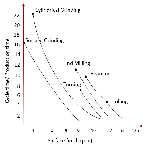
Figure 3
As we know, cycle time increases in case we must achieve good surface finish. Typically, the cost doubles if we double the surface finish value, hence the designer should take care before mentioning the surface finish value, & it should be justifiable. Saving one minute of machining time on one part will save exponential cost for mass production.
Trends are changing – people are moving from document centric design towards model centric design. Nowadays, design & manufacturing teams jointly work and understand all aspects of design & manufacturing process. To achieve the objective of true ‘Digital Twin’, many organizations have already initiated an MBE based approach.
DFMPro supports PMI based rules – few are listed below & many more of such best practices will come be supported in upcoming releases.
Roughness Value.
Recommended Tolerance for Holes.
Recommended Hole Distance Tolerance.
Linear Tolerance Check.
Molding Tolerance.
Bend Radius and Allowable tolerance range.
Such DFMPro checks help predict the quality of the part, get early visibility of downstream issues and better cost estimates to make sure that superior products are created faster delivering higher value to customers.
Want to know more about how DFMPro can help you in organizational MBE initiative? Stay tuned for upcoming articles. Write to dfmpro.marketing@hcl-software.com for more details.